
2018_htpd_iallfrey_final_v3_hg
P. 1
Bt
J×B
JGun
Poloidal Field
Toroidal Field
59.35 61.88 40.70
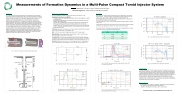
Measurements of Formation Dynamics in a Multi-Pulse Compact Toroid Injector System
I. Allfrey, T. Matsumoto, T. Roche, H. Gota, E. Garate, and the TAE Team
TAE Technologies, Inc., 19631 Pauling, Foothill Ranch, CA 92610 Results:
Abstract:
The C-2W experiment at TAE Technologies aims at sustaining an advanced beam- driven field reversed configuration (FRC) plasma. However, FRC lifetime is limited by particle confinement, among other factors. Injecting a supersonic compact toroid (CT) through the separatrix radius (Rs) is a means of refueling the FRC’s core with deuterium. For long-lived plasmas there is a need for multiple, non-disruptive, refueling events with uniform CTs. To develop a consistent and repetitive injection system a dedicated test bed exists to study formation dynamics, as well as translation and merging of CTs. The test bed is outfitted with a diagnostic suite including B-dot probes, a triple probe, an interferometer, Rogowskis and a collimated fiber optic array to measure plasma parameters such as electron density (ne), electron temperature (Te) and magnetic fields, in addition to macroscopic attributes such as CT velocity, volume and particle count. Neutral gas build-up has been mitigated, in part, by the adoption of a plasma source for pre-ionization which assists the compact toroid injector (CTI) breakdown and increases the ionization fraction. Particulars of pulse to pulse repeatability, which is affected by the accumulation of neutral gas, lingering plasma and pulsed power supply variations are discussed.
Materials and Methods:
The CTI is designed to operate in a burst of five pulses at a rate of up to 1 kHz.
Magnetized Coaxial Plasma Gun (MCPG):
• The MCPG consists of coaxial electrodes between which neutral deuterium is injected via tangential ports.
• When the gas is distributed the bias magnetic field and main discharge circuitry are triggered, with arbitrary timing.
• The main discharge applies high voltage across electrodes which breaks down the injected gas forming plasma that is accelerated by JxB self-force. The toroidal magnetic field in the CT is provided by up to 200 kA of current in the main discharge.
• As the CT accelerates through the bias field it accumulates poloidal flux, creating the spheromak-like structure.
Puff Valves: Neutral gas is introduced via of Parker Hannifin 009-1643-900 fast solenoid valves, which can operate at 3.5 ms repetition rate.
Bias: ~100 G iron-core solenoid magnet, powered by a 2 A DC power supply.
Main Discharge: -10 kV charge voltage, 125 μF capacitor, 6.25 kJ of stored energy.
Peak current up to 200 kA with a 10 μs rise time.
Pre-ionizer (PI): The PI provides a seed plasma which limits the required neutral gas, increasing ionization fraction, which effectively limits the residual neutrals. Additionally it decreases the breakdown delay and jitter allowing for better synchronization of the CTs.
Diagnostics: Rogowski coil for gun current, triple Langmuir probe for localized edge Te and ne, interferometry for line-integrated ne, and a PMT array for time of flight (TOF).
Peak density, as measured by the Langmuir probe, for the third pulse is ~30% higher than the second. Changes in density are explained by lingering neutral gas from the previous CTs. This is evident in the long “tails” of plasma that follow the CT. Line-integrated density, from interferometry, shows an increase in 57%, indicating that the core density increases more than the edge.
The radius of the first CT is too small to be measured as the Langmuir probe is located near the wall.
Temperature measurements by triple Langmuir probe at the edge of the plasma indicate that the electron temperature exceeds 40 eV, which is the limit of the probe.
The velocity of the CTs decreases during a sequence, which is explained by in increase in mass due to excess neutral gas from previous pulses.
1021
1020
1019
18
Density, Langmuir
Signal(kA)
ne ⇥1020 (m�3 )
Signal(A. U.)
Temperature(eV) ne(m�3)
Pulse
1 2 3
Velocity (km/s)
Kinetic Energy (J)
487 292 131
1017
0 20 40 60 80 100
Time(μs)
Fig. 7: Local edge density measured by the Langmuir probe.
Electron Temperature, Langmuir
10
Pulse 2
Pulse 3
A
Drift tube
MCPG
Expansion chamber
Fig. 1: Cartoon of the compact toroid (spheromak) formation process.
20 10 0
Conclusion:
Interferometer PMTs
+Z
Pre-ionizer
Fig. 2: Drawing of the CTI showing the main components and diagnostic locations.
Fig. 3: Simplified schematic of the main gun power supply showing two pulse circuit.
Fig. 5: Plot of TOF array, where solid lines are the signals from the first PMT and dashed are the second.
Triple probe B-dot
Iron core
Bias magnet
Puff Valve
Ceramic break
10 20 30 40 50 Time(μs)
0 20 40 60 80 100 Time(μs)
Fig. 8: Te as measured by the Langmuir probe at the edge.
To use a multi-pulse CTI for FRC refueling consistent CT generation is necessary. A pulse to pulse comparison of the formation dynamics in a well-diagnosed multi-pulse CT injector has been presented, which is affected by inconsistencies in pulsed power, lingering neutral gas and plasma, etc. Efforts to increase pulse to pulse consistency have been introduced, such as the pre-ionization system to limit excess neutral gas, a DC Bias magnet to eliminate pulse to pulse droop and high repetition-rate gas introduction system. Despite such efforts/features the inconsistency in neutral gas remains an issue. And as consistent CTs are necessary for consistent and predictable refueling this effort requires further investigation.
Future Work:
�10 kV
Rload
Lload
100 0
Pulse 1
Pulse 2
Pulse 3
4 2 0
Pulse 2
Pulse 3
Rcharge
Rcharge
125 μF
RG213
RG213
Pulse 2
125 μF
Electrode Current
Density, Interferometer
0 20 40 60 80 100 Time(μs)
Fig. 4: Main gun current measured by Rogowski coil. First pulse can see breakdown delay and second and third pulses are not crowbareed.
0 10 20 30 40 50 60 Time(μs)
Fig. 6: Line-integrated density measured by the double pass interferometer. The signal from the first CT is too noisy.
• •
Improvements to the neutral gas consistency: optimizing the system parameters, more precise gas introduction and better gas utilization.
Upgrades to the diagnostics including ne and Te measurements.
Presented on Apr 17, 2018 at HTPD 2018, San Diego, CA
1.00 0.75 0.50 0.25 0.00
Pulse 1
Pulse 2
Pulse 3
40
30 Pulse 3
Velocity
| 1 |
