
Demo
P. 1
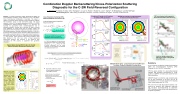
 Abstract: A versatile combination Doppler Backscattering (DBS) and Cross-Polarization Scattering (CPS) diagnostic for the C-2W Beam- Driven Field-Reversed Configuration is described. This system is capable of measuring density fluctuations and perpendicular magnetic field fluctuations across a wide wavenumber range, with typical resolution Dkq/kq≤ 0.4. Four tunable frequencies (26 GHz ≤ f ≤ 60 GHz corresponding to plasma densities 0.8x10¹⁹ ≤ ne ≤ 3x10¹⁹m-3) are launched via quasi-optical beam combiners/polarizers and an adjustable parabolic focusing mirror selecting the beam incidence angle. GENRAY ray tracing shows that the incident X-mode and backscattered CPS O-mode beam trajectories essentially overlap for C- 2W plasma parameters, allowing simultaneous detection of ñ and Bq or Br from the same scattering volume. We discuss DBS measurements of the toroidal wavenumber spectrum of gyro-scale density fluctuations in the previous C-2U FRC (0.5 ≤ kqrs ≤ 10 with the ion sound gyro-radius rs). Only low-level, high-k (electron-scale) density fluctuations have been detected in the C-2U core, while a broad exponential wavenumber spectrum was observed in the scrape-off layer surrounding the FRC plasma, in agreement with gyrokinetic simulations.
Doppler Backscattering (DBS) Provides the Toroidal Density Fluctuation Wavenumber Spectrum ñ(kq)
General equation for scattered electric field Es:
Cross-Polarization Scattering (CPS): Measuring Magnetic Fluctuations (Br)
X-mode and O-mode cut-off locations GENRAY ray tracing of incident/scattered
FRC core plasma inside separatrix: Decreased fluctuation level at low kρs
Low-k ion modes reduced by almost two orders of magnitude intheFRCcore
Summary
• A new 4-channel combination Doppler Backscattering (DBS) and Cross-Polarization Scattering (CPS) Diagnostic for the C-2W FRC is described.
DBS/CPS can probe toroidal wavenumbers kq =1-15 cm-1 (via adjusting the toroidal launch angle). Axial FRC contraction cau- ses a finite axial mismatch angle that will be compensated via two-axis adjust- ment of the focusing mirror.
26-60 GHz tunable Ka, U-Band sources cover densities 0.83 - 4.4x10¹⁹ m-3
D
X,Y Plane Ray Trajectories
Ray Tajectories for varying
n
§ Geometric Criterion for return of backscattered radiation to (monostatic) receiver:
fL: Mismatch angle of launched beam
f0: Mismatch angle at turning point
k : Measured (resonant) density fluctuation n
wavenumber
ax: Gaussian beam width
2
Typically requires
f ≤3-5o L
CPS 26-40 GHz • X-mode receive
CPS has great potential for wavenumber-resolved magnetic field fluctuation measurements in C-2W, guided by GENRAY ray-tracing and (soon) full-wave code calculations.
40 20 0
-20 -40
2
1
-10
-20
φ =0
φ =2o
3o Launch
42473 2.5 ms
-30 33 GHz -40
L
φ =4o
φ =8o
Turning point (cutoff)
-40
0
x (cm)
20
-2
0
7.3
12
Rs
-20
U
Ka
40
-50 -60 -70
X-mode. 47.7 GHz 42473
2.7
z (cm)
Two-axis alignment of focusing mirror via dual stepper motor control
O-mode DBS launch/ receive (40-60GHz)
48 GHz
CPS X-mode receive (40-60 GHz)
O-mode 26-40 GHz DBS launch/receive
• DBS/CPS: Need to control the axial mismatch angle due to axial contraction of the FRC; this will be accomplished via a two-axis mount for the focusing mirror (under development for C-2W).
• FRC Core: No ion-scale (large-scale) turbulence; near classical ion transport. SOL: Moderate, multi-scale SOL turbulence observed/predicted by Gyrokinetic (GTC) simulations (driven by the radial density/electron temperature gradients).
40 GHz
sin(φ0 ) ≤ k a n x
axial mismatch angle φ 0
Combination Doppler Backscattering/Cross-Polarization Scattering Diagnostic for the C-2W Field-Reversed Configuration
L. Schmitz1,2, B. Deng1, H. Gota1, M.C. Thompson1, C. Lau3, D. Fulton1, I Holod2, Z. Lin3, T. Tajima1,3, M. Binderbauer1, and the TAE Team 1TAE Technologies, Inc., 19631 Pauling, Foothill Ranch, CA 92610, 2University of California Los Angeles, 3University of California Irvine
Incident/scattered electric field Eii, Es: Induced current J(i):
40 20 0
40
20
0
60
40 20
40
20
0
-20
RRFR
42 GHz
O (DBS)
X (CPS)
40
20
0
-20
-40
(b)
28 GHz
O (DBS)
X (CPS)
ne (1019 m-3)
y (cm)
R (cm)
f (GHz)
f (GHz)
f (GHz)
y (cm)
y (cm)
$ω ' −∇×∇×E+ i
2$'
∂J(i) o∂t
σ
( s)&%c)(&%iεω)(s
1−
iεω2 ñ ω + ! -
E=−iμ J(i)= 0 pe E+ i σσE×B/B
fco
" ˆ ( ˆ $ E ( ω , k ) = k × k × E )
− y 2 / a 2y
(()x ins ins sd)
s s s #s 2#&
si
$nx0' dI / ds~n! (k , s)e$− 2 '
DBS/CPS Beam Optics - Lensed Scalar Horns with Wire Grid Polarizers; Parabolic Adjustable Focusing Mirror
0i
fcx
i2,i.k
ωi ne εoωpe
The second (highlighted) term describes
the induced current in the opposite polarization and is proportional to Br
In C-2W, the trajectories of launched and backscattered X-mode and O-mode nearly overlap (as wpe >> wce). Hence the CPS (O-mode) component can be easily separated out via polarizers and detected via a dedicated receive horn
I ω,k kS
Ttot=3keV Be=0.2T
Rs
Rs
r 0 %16π4 aa
00 20 40 60 R (cm)
Poloidal mismatch angle f0: ki • B = cos(π /2-φ0 )
DBS/CPS Diagnostic Positioning on C-2W
xy " k 2a2sin2(φ )%
∫ d ω d t d k d x n! ω k nnnn
− x 2 / a 2 e
e
− i ( ω + ω − ω ) t e
e
i ( k + k − k ) x
− i ω R / c e
I
I
kθ
X-Mode
ω =ωi-k v
s θ ExB
ks=ki-kθ
-40
-40 -10 20 50 -40 -10 20 50
ζ
O-Mode
DBS Launch/ Receive
(a)
Polarizer
fco
x (cm)
Back-scattered X-mode CPS return
O-mode Launch
x (cm)
Back-scattered O-mode X-mode CPS return Launch
Launch angle ζ= 4o, 8o, 15o Probed kθ: 2.1, 4.5, 9.2 cm-1
CPS receive
for different FRC parameters
O-mode and X-mode CPS return
(a)
(b)
(c)
Ttot=1keV Be=0.1T
Probing Fluctuations inside the Separatrix
Probing Fluctuations in the Scape-Off Layer
fce
f ce
R0 Rs fce
R
0
R0
fco
fcx
Heterodyne U-Band Receiver
(2 ch, dedicated DBS and
CPS Paths)
Ttot=10keV Be=0.5T
fcx
Launch angle ζ= 4o, 8o, 15o Probed kθ: 1.3, 5.2, 10.7 cm-1
L
L
L
L
| 1 |
