
poster v1
P. 1
Introduction
An array of diagnostics was installed across the divertor electrode plates of C-2W.
They are well-situated to study electron heat transport on the open field line plasma that surrounds the FRC.
Electrostatic energy analyzers, pyrobolometers and thermocouples can measure the particle heat flux, ion current density, and ion energy distribution.
Confinement Vessel
Divertor Vessel
Installed Diagnostics
Energy Analyzer Construction
Electrode Design
Electron and ion grids composed of frame and “pill- box” shaped electrode.
Spacer rings also serve as baffles to shield alumina baseplate from stray particles.
The C-2W Experiment
CV
(a)
1 SOL Mirror
.5
540μ m
⌀4mm
FRC core surrounded by a mirror confined “scrape 1.5
Inner Divertor
Formation Section
Electrodes
Electrodes
Outer Divertor
10
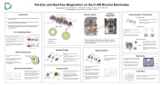
Particle and Heat Flux Diagnostics on the C-2W Divertor Electrodes
M. E. Griswold, E. M. Granstedt, M. C. Thompson, K. Knapp, B. Koop, and the TAE Team Tae Technologies, Inc., 19631 Pauling, Foothill Ranch, CA 92610
Formation Section
frame
mesh
Inner Divertor
Outer Divertor
spacer
mesh
spacer
Attenuation grid laser-cut from 75 μm thick
tungsten sheet. m
Conical holes with 54 deg. taper avoid collimating ions.
Two different hole patterns track changes in aperture area caused by titanium coating.
Attenuation Grid
540μ
⌀1.3
mm ⌀3
mm
Pattern #1
Pattern #2
⌀100μ mm
⌀200μ
Radius (meters) Radius (meters)
off layer” plasma on open field lines.
Open field lines extend past a mirror at either end of the CV into divertor vessels.
Field lines connect to divertor electrode plates inside each divertor vessel.
Two configurations: field lines mostly connecting in either the inner or outer divertor (see adjacent figure).
energy analyzer bolometer thermocouple
Energy Analyzers, Bolometers, and thermocouples were installed across the electrode plates in the inner and outer divertors.
High Voltage Design
Four concentric electrode plates in each divertor.
Plates are electrically isolated from each other and can be biased to introduce a radial electric field in the plasma.
Each plate has two bolometers, two electrostatic energy analyzers, and two type- E thermocouples.
isolated, concentric electrode plates
diagnostics
screw-on cap
2.41”
current sensor electron grid
ion grid
attenuation grid
Attenuation grid welded to screw-on cap.
Current sensor, electron grid, and ion grid attached to baseplate with ceramic cement.
Electronics
grounded cabinet
HV insulator
Rack mount frame
Isolation transformers
v⟂
v||
Ion Loss Cone
loss cone boundary
v⟂
v||
Electron Loss Cone
Heat transport on C-2W’s open field lines governed by convective transport through the mirror.
In an ideal mirror, an ambipolar electric potential modifies the loss cone so electrons are lost at the same rate as ions. Thermal energy carried away by electrons is only (5-6) Te per ion that is lost.
Cold electrons from the edge can destroy ambipolar confinement, leading to free-streaming electron losses of ~40 Te per ion.
LiTaO3 crystal
V = IpR
!
!! = !"# × !
Pyroelectric LiTaO3 crystal, mounted on springs to isolate the crystal from vibration
Pyroelectric materials have permanent polarization that varies with temperature, causing polarization current proportional to the incident power density.
Broad frequency response (100-200 kHz) and can withstand high heat loads (20 MW/m2).
Divertor Electrodes
mounting structure
alumina baseplate
pyroelectric crystal
Modular design simplifies installation and maintenance.
Signal cables terminated in connector plug that attaches to mounting structure.
Internal components built on alumina baseplate that plugs into mounting structure.
Screw-on cap completes the diagnostic enclosure.
Electron heat transport
Pyrobolometer
Current sensor positioned behind three gridded electrodes.
Attenuation grid reduces incident plasma density 30x to prevent space charge effects in the device.
Electron grid biased below case potential to repel plasma electrons and suppress secondary electrons from current sensor.
Ion grid biased to repel plasma ions. Bias can be swept to measure the ion energy distribution or set to zero to measure ion current density.
current sensor
secondary electrons
e. grid
!(x)
ion grid
atten. grid
high energy ions
low energy ions
electrons
loss cone boundary with positive ambipolar potential
0
FRC Core
Designed to hold -1 kV on electron grid and +4 kV on ion grid in small device.
Maximum electric field: 1 kV/mm along insulator surfaces, 3 kV/mm in vacuum gaps.
Interface between metal and ceramic designed to minimize electric field at triple point junctions.
1.5
1 SOL
.5 0
6 cm
field suppressed at triple points
(b)
Mirror
0 FRCCore5
Cylindrical axis (meters)
connection to signal cables
connection to signal cables
Each electrode plate can be biased 5 kV from machine ground with inductive voltage spikes up to 25 kV.
All electronics float at the potential of the electrode plate to which they are connected.
Housed in isolated HV modules with power provided through isolation transformers.
Initial Data
springs isolate the crystal from vibration
Incident power, Q
Diagnostics have been installed on the machine, electronics system is partially operational.
Initial data from central electrode in the North outer divertor shows ion current density and power density traces.
Modular Design
Energy Analyzer
1.5 cm
sensor module
mounting structure
alumina baseplate
| 1 |
