
FIDA Diagnostic Development for the C-2W Field-Reversed Configuration Plasma
P. 1
D D
Before Filter Magnet
50 mm
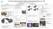
After Filter Magnet
• •
Introduction
A high-confinement operating regime with plasma lifetimes significantly ex- ceeding previous empirical scaling laws was recently obtained by combining plasma gun edge biasing and Neutral Beam Injection in the C-2U field-reversed configuration (FRC) experiment[1].
1)TAE Technologies, Inc., P.O. Box 7010, Rancho Santa Margarita, CA 92688, USA 2)Budker Institute of Nuclear Physics, 11 Acad. Lavrentyev Ave., Novosibirsk 630090, Russia
Ion Source Characteristics Beam Characteristics
Future Work
•
•∼10 hoursoperationlifetime
Remaining Questions
An improved ion source will permit answering the following questions:
• Is the drift grid necessary?
Will focusing systems be required at the source?
• Will the beam lens system be required?
Will further simulations be required?
Why apparent drop in beam current for >10 keV?
Absolute calibration is desirable for diagnostics sensitive to charge-exchanged ions, including those originating from Neutral Beam Injection.
detector
detector
detector
detector
HWPES-250 Hollow Dispenser Cathode System[4]
ab
20 0
0
0 50 100 150 200 250 0 500 1000 1500
Pyrobolometer Calibration
NPA Calibration
Lithium Tatalate (LiTaO3 ) pyro-crystal ∼3×10⁻⁸Acm2/W→
require 20 μA cm− 2 beam current
Simultaneous H0 and D0 detection
E /E =∼30 max min
E ≤60keV max
He stripping cell
MCP detection system
39 channels per isotope (78 total) ∼10−12 A input sensitivity → require ∼1nAcm−2 beamcurrent
• neutral particle analyzers (NPA)[2]
• neutral particle bolometers (NPB)[3] • Pyro bolometers
• Visible and UV bolometers
• Plasma discharge → emission current not space-charge limited
The purpose of a Calibration Ion Beam (CIB) system is to provide a beam of ions suitable for calibrating such diagnostics against neutral particles.
Ion Source Circuit Diagram
ie id ii αii (1 − α)ii
Ion Source Cross-section
3 20 27
Heater Power vs. Temperature
4
147
50 40 30 20 10
0
• • •
15 10 5
• • • •
z = 147mm z = 249mm
•
• •
LaB heater insufficiently reliable (∼ 300 hrs) 6
• Beam divergence: < 2◦ half-angle
• Performance of filter magnet is uncertain
• Exploring commercially available hollow dispenser cathode [4]
• Heater filament failed due to hydrogen embrittlement • LaB temperature about 1500 K
•
Saturated phosphor plate provides limited indication of beam profile be- fore and after filter magnet
[1] [2] [3] [4]
H. Gota et al. Nuclear Fusion 57.11 (2017), p. 116021.
R. Clary et al. Review of Scientific Instruments 87.11 (2016), 11E703.
R. Clary et al. Review of Scientific Instruments 83.10, 10D713 (2012), p. 10D713. HeatWave Labs, Inc. HWPES-250 Hollow Cathode System, http://cathode.com.
•
• • •
AB
Transmission of coatings is
thickness & energy dependent
Calibration with neutral beam differs
greatly from expectation
CIB should provide more reliable
calibration −1
CIB Overview
df e
c
a. Ion source
b. Ion extraction
c. Filter magnet
d. Acceleration gap
e. Electrostatic quadrupole lens
f. Target chamber
• Ion source produces < 100 μA cm− 2 at source, insufficient current density
• for calibrating pyro-bolometer and AXUV detectors
100
∝ V3/2
0.2 A W sensitivity → require
An Ion Beam System for Absolute Calibration of Neutral Particle Detectors for C-2W
• In-house and versatile
V D3
• •
ih
40 20 0
Hydrogen or Deuterium beam
> 95 % of primary isotope, oligomer
(no fractional energy component)
Wide current range (up to
100μA/cm2) D1 Sweepable 3 keV to 60 keV
Characterized divergence & current
Stable, repeatable, & reliable
R. Clary1, A. Perstin1, S. Korepanov1, A. Kolmogorov2, V. Davydenko2, A. A. Ivanov2, G. Shulzhenko2, the TAE Team
Summary of Ion Source Characteristics
z = 147 mm
z = 249mm
z = 532 mm
z = 147mm z = 249mm
−10 0 10 Vertical (mm)
A
Measurement Polyenergetic Monoenergetic
0 5 10 15 20 25 Beam Energy (keV)
V
Space-Charge Limited
Profiles measured at 147 mm, 249 mm, 430 mm and 532 mm Amplitude and width are determined from 5 channel faraday cup Beam size reveals non-linear affects of magnet filter
Heater Current
0.81AσT 0 sccm 4 sccm
10 μA cm
−2
beam current
80 8.10 A 8.25 A 60 8.35 A 8.40 A 40 8.50 A
60 40 20
∝ z Horizontal Vertical
100 200 300 400 500 600 Effective Beam Length (mm)
102 101 100
∝ 1/z2 Horizontal Vertical
Cathode Potential (V)
Temperature (°K)
id
AXUV Calibration
• • • •
• •
AA
Improved Ion Source
• Ion beam current to total ion current scaling consistent with divergence • Ion current scales linearly with emission current
• Emission current is space-charge limited
• Ion grid efficiency ∼15 %
• Ion current : emission current < 0.5 %
• Beam current : emission current < 0.08 %
•Heaterpower8.5A×8.5V=72W(80%) z=430mm •Emissionpower0.1A×175V=18W(20%)
Ion Grid
Drift Grid
Cathode Grid
LaB6
9.9 kΩ
Emission Current (mA)
Heater Power (W)
Beam Radius (mm)
Current Density (μA/cm2)
Current Density (μA/cm2)
Current Density (μA/cm2)
Responsivity (arb.)
+
−
ic
Ph Pc D2 Pi
• Space-charge limited electron emission also limits ion production
102
103
Gas flow does not affect LaB
Ion Source Heater Reliability
6
temperature
Effective Beam Length (mm)
6
• Estimated lifetime ∼ 300 hrs
−10 0 10 Horizontal (mm)
0.20 0.15 0.10 0.05 0.00
Divergence < 2◦ half-angle → T ∼ 5 eV at 3 keV extraction energy i
• •
Current density ∝ z−2 → 10× drop at target
1/ 2 & 1/ 3 energy components → 10× drop in current density Faraday cup insufficient to resolve beam properties near beam axis
•
• Up to ∼10 mA ion current extraction
4
| 1 |
