
RSmith_HTPD_2018_April_4_hg_final (1)
P. 1
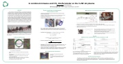
A combined mmwave and CO2 interferometer on the C-2W Jet plasma
Roger J Smith and the TAE Team
TAE Technologies, Inc., 19631 Pauling, Foothill Ranch, CA 92610 Physics results from Jet Interferometer
Critical Issues for C-2W
Interferometry will quantify the jet electron density which has a bearing on particle inventory of the FRC plasma.
Interplay (correlations) between jet plasma inventory and 1) biasing Scrape-off Layer, 2) operation of distant divertor, and 3) operation of flux expansion divertor.
Size and shape of the jet plasma.
Instabilities present in the Jet plasma ne can be measured to bandwidths of 60 MHz.
Fig. 3 Jet interferometer is located in the mirror region. An array of seven ports allow tangential views of both the translating FRC and the jet plasma. The 3 CO2 and 2 mmwave quasi-optical chords are shown. Impact parameter is stepped by 8.9cm (3.5”).
Abstract
The C-2W device at TAE Technologies is now operational and represents another major step in a progression of advanced beam-driven Field-Reversed Configuration (FRC) confinement devices that have prolonged the lifetime, increased the stability and have added significant neutral beam injection power to heat and sustain an FRC plasma. Crucial to plasma sustainment and increased lifetime is an understanding of the Jet plasma and X-point dynamics. A novel two-color multi-chord tangentially viewing interferometer has been designed and built to provide line averaged density at both 10.6 μm mid-infra-red and 1000 μm millimeter-wave wavelengths. This combination of sources allows a generous measurement dynamic range. The Jet interferometer is positioned in the mirror region of the confinement vessel (CV) to capture the initial high- density translated FRC source, the establishment of the Jet outflow from the merging of the two FRCs in the CV and the steady-state Jet plasma for the duration of the discharge which is expected to be of low line averaged density.
Fig. 1 North side of C-2W showing the Confinement Vessel (CV), Inner Divertor for flux expansion.
C-2W Jet Interferometer
Millimeterwave Interferometer Performance
• •
• •
• • • •
Fig. 5 Electronic schematic and Tx units mounted on frame
Mmwave source is based on low phase noise dielectric resonant oscillators (DROs) Elva-1.com.
The DROs are 7.5 GHz sources and Impatt multiplication is used to reach 150 GHz and 2nd harmonic mixing for 300 GHz operation. 5 MHz and 30 MHz BWs for CO2 and millimeter wave interferometers.
Millimeter wave source is novel.
Fig. 6 Z-cut crystalline qtz windows on 3 3/8” CF have been procured to give maximum aperture when mounted to a 2 3⁄4” CF ports.
Qtz windows have been AR coated to give a transmission of > 88% per window. Parylene is a stable high vacuum material.
The Rx and Tx units are coupled with a free space quasi-optical beam of about 1 m between Rx and Tx lenses.
Results
Millimeter wave interferometer recently installed on C-2W
•
•
• •
Sensitivity of the interferometers: l = 10.6 μm for CO2 and 1 mm for 300 GHz. j ! = 2.82&10)*+l∫. / ! 12 + 24 �2/l [r71]
-0
j9:; =17.1°/10*=>); j?? = 1620°/10*=>);
1° phase shift = 4x10¹⁶ (1 mm) and 4x10¹⁸ (10.6 μm) m-2 ne cutoff = 1.1x10²¹ m-3 (l=1 mm)
Two colors, movement Dl can be eliminated: 10.6 μm CO2 and 1 mm.
. j − l; j A/012=* l*;×
1
1 − l;; /l*;
j − 94.3j ~* ;
3.0&10)*+
- 2.82&10)*+l*
Fig. 2 Layout of the interferometer
• Mechanical structure is a braced by an upper G10 brace and shear walls.
• Two millimeter wave (1mm) interferometers and three CO2 (10.6 μm) interferometers.
• A reference CO2 interferometer for quantifying the common phase noise from the Bragg AOM.
• Both translating FRC and jet plasma are measured, with overlapping mmwave/CO2 chords on two adjacent mid-plane ports.
• Some spatial information from Abel inversion.
Redundancy: Both wavelengths overlap for jet plasma and translating FRC (CO2). CO2 interferometer will probably become insensitive to Jet plasma and mmwave is overly sensitive to FRC but should be in transmission for FRC.
Slew rate of interferometers: A translating FRC at 300 km/s, lengths of 1 m and a peak density of >1021 m-3 will have a change in phase of 12,000° in 5 microseconds. The two interferometers must accommodate a frequency bandwidth of 70 kHz and 7 MHz.
CO2 InterferometerPerformance
Fig. 4 Three CO2 interferometer detected 40 MHz beats.
The signals are fed into a quadrature mixer and the sine and cosine signals at base band are digitized.
Fig7.Shot105298onlyoneinterferometerworkingbutthejet plasma was successfully measured for the first time.
Line-integrated density (LID) is 7x10¹⁹ m-2 and stable until the plasma develops an n=1 instability and discharge ends.
Fig8.Shot105313:bothmmwaveinterferometersworking.Atimedelayof0.68μsin arrival of FRC due to the 9.5 cm axial offset yielded a plasma velocity >140 km/sec. Cutoffs at 4 and 7x10¹⁹ m-2 gave approximate plasma diameters of 40 and 65 cm. Phase slew rate of 11000° in <30 μs.
Summary and Conclusion
The millimeter wave interferometers have been temporally installed on C-2W to test and have successfully measured the line- integrated density of both the translating FRC and the jet divertor plasma. It has been shown that the millimeter wave enters cutoff and the CO2 system will be necessary and provide complementary data. It is expected that the full interferometer systems will be operational in the following months.
| 1 |
