
Page 2 - Design of a custom insertable probe platform for measurements of C-2W inner divertor plasma parameters
P. 2
10J115-2
DuBois et al.
Rev. Sci. Instrum. 89, 10J115 (2018)
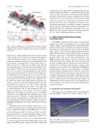
FIG. 1.
field configuration (black) and plasma density (color contours) calculated from an MHD code. The flared field configuration reduces the particle and heat loss from the SOL.
inner divertor could potentially strike the electrodes and emit cold secondary electrons back into the plasma. The behavior of the SOL plasma is similar to that of mirror machines,12 and mirror experiments suggest that a flared magnetic field in the divertor can suppress the cooling effects from sec- ondary electrons13,14 and reduce the high particle flux by decreasing the density in the inner divertor compared to the mirror throat.15 The decrease in density leads to the forma- tion of an electrostatic potential distribution in the divertor that maintains quasineutrality so that the electron energy loss is comparable to the ion energy loss.15 As long as the elec- trostatic potential maintains a small fraction of the potential drop near the divertor electrode plates, the ambipolar elec- tric field that forms in the plasma sheath can prevent low energy secondary electrons from exiting the divertor because the potential well cannot be overcome.14 On the other side of the potential distribution, the majority of electrons will be reflected back into the CV, thus keeping the SOL elec- trons hot. Neutral gas in the divertor can become ionized and generate low-energy electrons that can also cool the SOL electrons, so it is equally important to maintain low recycling in the inner divertor. Therefore, the high temperature of the SOL electrons is maintained by controlling the electrostatic potential distribution using a flared field configuration and sus- taining high pumping speeds to reduce neutral gas in the inner divertors.
The divertor houses electrode plates which serve to con- trol the SOL rotation via E × B velocity shear, which is well known to suppress instabilities.16 The FRC plasma core rotates
in the ion diamagnetic drift (⇀vDi) direction, which can lead to the growth of the n = 2 rotational instability, leading to a sig- nificant decrease in the plasma confinement.16 In C-2U,17 it
was shown that an E × B velocity (⇀vE×B), which opposes the
via generated velocity shear. The use of plasma guns was also found to mitigate the initial n = 1 wobble mode via line tying to the electrodes.11 In an effort to negate the growth of instabil- ities that are detrimental to plasma confinement in C-2W, the electrode plates are biased to produce an inward electric field
so that ⇀vE×B opposes ⇀vDi. Plasma guns located in the outer divertors may also be used to facilitate the electrical connec- tion between the plasma core and the electrodes to maintain edge biasing. It is evident that the dynamics in the inner diver- tors greatly affect the confinement and stability of the core FRC plasma. Consequently, spatially localized measurements of Vp, ne, and Te in the inner divertors are crucial.
III. INNER DIVERTOR INSERTABLE PROBE PLATFORM (iDIPP)
The iDIPP is comprised of a heavy duty rack and a pinion motion system with a travel length of 1.9 m, custom coiled cabling, a unique segmented probe shaft, and interchangeable probe tips. The custom coiled cabling is attached to the extreme ends of the heavy duty transporter (end cap and custom shuttle flange in Fig. 2) and is routed through the internal transporter shuttle. The probe shaft connects directly to the custom shut- tle flange, and signals are transmitted from Kapton wires in the probe shaft to the custom coiled cable through a 9-pin PEEK (polyether ether ketone) connector. At the other end of the probe shaft exists another 9-pin connector that various probe tip assemblies plug into. The motion system will trans- port the probes to different radial positions to obtain a radial profile over a series of shots. It is required that the iDIPP have an independent vacuum system for maintenance or changing probe tips without venting the divertor. Therefore, a gate valve will be mounted between the motion system and the diver- tor flange. An interlock system will be employed to prevent a collision between the probe and gate valve. The gate valve will also shield the probe shaft and probe tips during wall conditioning processes between shots. An in-depth discus- sion on each part of the system is presented in the subsequent sections of the paper.
A. Heavy duty rack and pinion transporter
The main component of the inner divertor insertable probe platform (iDIPP) is the motion system, shown in Fig. 2.
FIG. 2. The iDIPP custom motion system consists of a heavy duty rack and pinion transporter from the Kurt J. Lesker Company and a magnetically coupled drive manufactured by UHV Design Ltd.
(a) The C-2W FRC device. (b) C-2W magnetic field lines in a flared
⇀v
improved the FRC particle transport and global confinement
Di
direction, greatly reduced the bulk plasma rotation and
