
Page 4 - Design of a custom insertable probe platform for measurements of C-2W inner divertor plasma parameters
P. 4
10J115-4 DuBois et al.
Rev. Sci. Instrum. 89, 10J115 (2018)
the coiled cable holds some tension while the motion system is in a retracted position. To prevent excessive strain on the cable when the ITS is fully extended, it was designed to be stretched to 4.5 m. A cable scoop, shown in Fig. 2, will be mounted to the back cap of the ITS to ensure that the cable assembly does not become pinched as it is retracting.
C. Segmented probe shaft
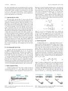
The probe shaft, shown in Fig. 6, connects directly to the front cap of the ITS and can be moved into the plasma for mea- surements of plasma parameters. The probe shaft has a 1.6 cm OD and is 1 m long. The probe shaft will pass 50.5 cm in front of biased electrodes which produce a radial electric field of 5 kV/m (maximum). To prevent shorting out the electric field, a segmented “fish scale” probe shaft has been designed. The segmented probe shaft is made of individual floating SST rings that are isolated from one another using ceramic disks. A ceramic tube runs down the inside of the shaft to insulate sig- nal cables from plasma facing components. A SST tube inside the ceramic tube serves to improve the rigidity of the probe shaft and provide additional shielding from local electric fields. Figure 6 shows a zoomed-in cross section of the segmented probe shaft with the layers visible. Nine UHV 30 AWG wires with Kapton insulation are run down the length of the probe shaft to transmit diagnostic signals to the coiled cable assem- bly. A variety of probe tips can be plugged into the end of the probe shaft.
D. Interchangeable probe tips
A variety of probe tip assemblies have been designed for the iDIPP to make measurements of ne, T e, V f , V p, ion tem- perature (T i ), and plasma flows. All probe tip assemblies are interchangeable without having to remove the entire system from C-2W. All probe tip assemblies are 4.8 cm long and 1.9 cm OD machined from alumina. At the end of the probe tip assembly, measurements are made with tungsten or SST probe tips. All of the probe signals are digitized at 80 MS/s, which gives the capability of measuring plasma parameters and associated fluctuations. In the four subsections below, a brief overview of designed and planned probe types is discussed.
1. Triple Langmuir Probe
A triple Langmuir probe18 has 3 tips to make real-time in situ measurements of V f , T e , and ne and provides an estimate of V p by sampling 3 points along the I-V characteristic trace.
FIG. 6. A model of the segmented probe shaft with a blown up section showing the internal structure.
Probe tip 2 remains floating and unbiased for a measurement of V f . The other two probe tips (tips 1 and 3) are floating and biased with respect to each other. The bias applied to tips 1 and 3 must be substantial enough for tip 3 to remain in the ion saturation regime (V bias > 2T e ). When tip 1 is biased to a larger potential (V + ), current will flow out of tip 3 and tip 1 will collect current. The absolute values of the currents flowing in and out of tips 1 and 3 are equal. Important plasma parameters can then be calculated using
Te = V+ − Vf , (1) ln(2)
Isat mi
ne=0.61eA kT, (2)
Te 4mi Vp=Vf+2ln3πm , (3)
e
where Te is in eV, A is the probe surface area, and the ion saturation current (Isat) is related to the voltages measured on tips 1 and 3. The iDIPP triple probe, shown in Fig. 7(a), has three 0.5 mm diameter tungsten probe tips that are spaced 2.7 mm apart and protrude 3 mm into the plasma, giving each tungsten tip an area of 2.7 mm2.
2. Gundestrup probe
A Gundestrup probe is a multi-tipped Mach probe,19 which is used to measure plasma flows using a pair of Lang- muir probes that are biased into Isat and physically isolated from each other using an insulator such as ceramic or boron nitride. Tips face opposite directions such that if the plasma has a flow velocity, the tip facing upstream will collect a higher Isat than the probe tip facing downstream since this tip is shielded from the plasma. Considering a magnetized plasma, diffusion is not the only mechanism at work for plasma flows and the ratio of these currents is related to the Mach number20 (M = Vflow/Cs) using
Be
I M −M cotη R=up=exp∥⊥ , (4)
Idown Mc
where Cs is the ion sound speed, Mc is the calibration constant, and η is the angle between the magnetic field and the probe tip. By using multiple pairs of probe tips, it is possible to resolve not only the flow speed of the plasma, but also the direction of the flow. The iDIPP Gundestrup probe, shown in Fig. 7(b), has 8 SST probe tips (3.2 mm long and 1.3 mm wide) that are biased to measure I sat , each facing a different direction and
FIG. 7. Models of various probes to be used on the iDIPP. (a) Triple Langmuir probe, (b) Gundestrup probe, and (c) Baffled probe.
