
Page 3 - Design of a custom insertable probe platform for measurements of C-2W inner divertor plasma parameters
P. 3
10J115-3 DuBois et al.
Rev. Sci. Instrum. 89, 10J115 (2018)
The iDIPP motion system consists of a custom heavy duty transporter with a linear rack and pinion system from Kurt J. Lesker Company (KJLC) and a magnetically coupled drive. The motion system is made of a stainless steel (SST) body that contains a rigid 5.1 cm diameter SST internal transporter shut- tle (ITS), highlighted in green in Fig. 2. The rack is mounted on the ITS, as shown in Fig. 2. The system was customized to provide 1.9 m of travel length with an overall total retracted (extended) length of 2.4 m (4.3 m) in order to reach the center of the inner divertor. The ITS is fitted with a custom shut- tle flange for the attachment of a probe shaft (discussed in Sec. III C).
The iDIPP system makes use of a magnetically coupled ultra-high vacuum (UHV) rotary drive and a stepper motor to extend/retract the ITS in/out of the divertor in 2 min or less. The MD40 “MagiDrive” rotary feedthrough, manufactured by UHV Design Ltd, is well suited for UHV performance and uses magnetically coupled motion that enables the transfer of motion into the vacuum environment. The MagiDrive contains two rotating rings with strip magnets mounted, so the poles are alternating. The air-side ring magnetically couples to the vacuum-side ring through a SST vacuum sheath such that the air-side north poles align over the vacuum-side south poles. A stepper motor (STM23IP-2EE NEMA 23 integrated drive) rotates the air-side ring, causing the vacuum-side ring to rotate. The vacuum-side ring is fixed to the pinion gear which rotates and drives the rack, incorporated into the KJLC linear rack and pinion drive, on the ITS in or out of the divertor. Magnetic reed switches will be utilized to track the extreme locations of the ITS.
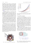
The iDIPP will be located on an 8 in CF port 45◦ below vertical on the south inner divertor, as is shown in Fig. 3. It was of concern that a system of this magnitude would have significant deflection when fully extended into the divertor. The ITS deflection due to gravity was modeled by KJLC for the iDIPP when mounted on the inner divertor port. The data in Fig. 4 show the deflection in mm as a function of the extension into the divertor for different weights attached to the end of the ITS. When the ITS is fully extended into the divertor with 10 lbs attached (black line), the deflection due to gravity is less than 7 mm. Realistically, the weight of the probe attached to the ITS will be no more than 1 lb (pink line), and the deflection will be no more than 3 mm.
FIG.3. AmodeloftheiDIPPmountedontheC-2Winnerdivertor.
FIG.4. Theinternaltransportershuttledeflectionduetogravityasafunction of extension length for different weights attached modeled by the Kurt J. Lesker Company.
B. Custom UHV coiled cabling
In order to get measurement signals out over the large length (maximum 4.3 m) of the iDIPP motion system, coiled cabling is necessary. Axon Cable provides custom coiled cables for UHV applications such as the space environment and magnetically confined fusion experiments and has designed a custom cable assembly with nine 50 Ω coaxial cables. Figure 5(a) shows a schematic of the cross-sectional view of the cable assembly. Each silver plated copper conductor of size 30 AWG is surrounded by a layer of extruded polyimide (Kapton) and is individually shielded by a silver plated cop- per braided shield, which will protect against frequencies less than 15 kHz. The outer insulation layer for the individual coax- ial cables is a polyimide (Kapton) tape. A layer of polyimide (Kapton) tape maintains all of the coaxial cables in place, with a PEEK braid outer insulation layer.
Figure 5(b) shows a side view schematic of the cable assembly with dimensions in mm. A length of 10 cm on each end of the cable assembly is left uncoiled to hold against the pull of the extended cable. The outer diameter (OD) of the cable assembly is 7.12 mm, and the coiled diameter is 20.1 mm. The resting length of the assembly is 1.9 m so that
FIG.5. AschematicdiagramoftheiDIPPcustomUHVcoiledcableshowing (a) the cross-sectional view of the internal structure and (b) the side view showing cable assembly dimensions. Dimensions are in mm.
