
Page 3 - A combined millimeter wave and CO2 interferometer on the C-2W Jet plasma
P. 3
10B110-3 R. J. Smith and TAE Team
Rev. Sci. Instrum. 89, 10B110 (2018)
one mmwave and one CO2, can vibrations and LID be sepa- rated, but it is expected that the movements will apply to the two other CO2 chords as well.
B. Millimeter wave interferometer
1. Electronic scheme of the mmwave interferometer
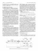
The millimeter wave system is a heterodyne interferome- ter using two low noise 7.5 GHz dielectric resonant oscillators (DRO) and impact ionization avalanche transit-time (Impatt) diodes as 40× multipliers to reach 300 GHz. A 2 MHz detuning of the receiving (Rx) DRO with respect to the fixed frequency of the transmitting (Tx) DRO produces a near 80 MHz RF IF out, as shown in Fig. 3 (Elva-1 Co.). The beat between the Tx and Rx sources is a sinusoidal RF output from the 2nd harmonic mixer. The output power is about 2 mW.
As originally intended, it was not possible to actively sta- bilize the RF IF 80 MHz beat which does drift as the DRO sources drift with time. Therefore, a tracking signal (LO IF out) is provided to monitor this spurious phase excursion. The phase difference between the RF signal and the LO tracking signal determines the resolution of the interferometer, a 10◦ rms phase noise with 30 MHz bandwidth (BW) over 20 ms.
The millimeter wave output is coupled using an antenna coupler from a fundamental waveguide to a free space Gaus- sian beam and focused to a waist on axis using high-density polyethylene (HDPE) lenses. The polarization is parallel to the external field (O-mode).
2. Demodulation of the plasma phase
The demodulation uses a “so-called” running phase tech- nique, which to this author’s knowledge has not been reported in the literature, in which phase traces are generated from the digitized RF signal and from a reference signal which may be the RF signal itself. The plasma trace is the difference of the two. This system required an LO tracking signal.
The phase noise floor for this method is determined by how steady the RF frequency is in time or how well the tracking signal tracks the RF phase. Heuristically, the RF 80 MHz beat is a phasor rotating at a measureable rate that is compared to a reference phasor rotating at a known rate. The accumulation of the phase of one phasor relative to the other is the desired phase
signal. As long as the relative rates between the phasors do not exceed 80 MHz, the phase is unambiguously determined. The running phase method eliminates the need of quadrature detection and the associated electronic equipment which may degrade the fidelity of the measurement. The method requires a high digitization rate of at least twice the highest spectral component in the signal to satisfy the Nyquist theorem. For this system, the data are digitized at 250 MS/s. The highest frequency component is 110 MHz, and the system bandwidth is 30 MHz.
The RF signal phase is given by
φRF(t)=(φRx − φTx) + φplasma(t) + φ∆l(t) + φspurious(t),
(4)
where (φRx − φTx) is a steady ∼80 MHz·2πt radians. The LO signal phase is given by
φLO(t) = (φRx − φTx) + φspurious(t), (5)
which is the interferometer phase signal without any contribu- tions from the plasma. Subtracting φLO(t) from φRF(t) is the desired φplasma(t) + φ∆l(t). The intrinsic, instantaneous phase noise is ∼1◦ which corresponds to a LID of 0.6 × 10¹⁶ m−2 as shown in Fig. 4. The noise in the accumulated phase is ∼10◦ at any time in a 20 ms acquisition (Fig. 5).
One can do no better in determining the accumulated phase traces of the RF and LO signals than by measuring the timing of the signal’s zero crossings and assigning a phase of π per crossing. The rate of zero crossings is ∼160 μs−1 and oversamples the phase traces. Accurately determining the time for each crossing is achieved by zero padding the signal in the frequency domain to generate more sampled points in the time domain and using 2-point linear interpolation. Zero padding by factors of 5 and 10 did not change the result of Fig. 4, which shows that the rms jitter in the half cycle duration is less than 1.5◦ relative to the average half cycle duration over 20 ms.
The phase noise of the interferometer after the elimination of the spurious phase using the tracking signal is 10◦ rms, an
16 −2 equivalent LID of 6 × 10 m .
C. The CO2 interferometer
The CO2 source is an RF excited laser (Synrad Co.) with an 11 W output polarized in the plane of the phenolic panel.
FIG.3. Electricalschematicofthemillimeterwaveinterferometer(Elva-1MMI-300R2).
