
Page 4 - A combined millimeter wave and CO2 interferometer on the C-2W Jet plasma
P. 4
10B110-4
R. J. Smith and TAE Team
Rev. Sci. Instrum. 89, 10B110 (2018)
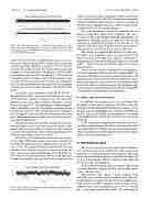
FIG. 4. Benchtop characterization of a mmwave system. The jitter in the time between zero crossings relative to the average half period for both RF and tracking signals in a 30 MHz bandwidth. The probe beam has more phase noise than the tracking signal.
About 1 W is split off to be divided between four CO2 inter- ferometers. The remaining 10 W is eliminated in a passively cooled beam dump. The laser is cooled to <20 ◦C for stable operation. The output is a Gaussian 3.5 mm diameter beam that expands to a 10 mm diameter at the detectors. Dichroic ZnSe beam splitters that pass 10.6 μm and have a 50% reflection coefficient at 633 nm are used to allow a HeNe alignment laser to follow the CO2 beams from source to detectors. All mirrors, detectors, and beam splitters lie in a plane with the exception of where the reference beam is shunted to the backside of the frame.
An acoustic optic modulator (AOM, Model #37040-5,
Gouch & Housego Co.) splits the laser beam into two using a
35 W RF driver (Gouch & Housego Co.). The first order
diffracted beam (scene beam) separates from the reference
◦
The optical components are fully contained in enclosures with interlocked covers to prevent accidental exposure to the beams. The laser output and power splitter are fully contained in an interlocked enclosure with re-entrant alignment posts to avoid exposure. Tubes connect enclosures.
About 92% of the angled scene beam is diverted to a series of two ZnSe 50/50 beam splitters and a mirror which direct the beams through the plasma at impact parameters of 0, 8.9, and 17.8 cm. The diameter chord is covered by both CO2 and millimeter wave systems to provide a comparison of the two phase traces and a robust determination of ∆l using Eq. (3). About 92% of the reference beam is steered to the other opti- cal panel and similarly split into three beams using two beam
FIG. 5. The residual phase noise from differencing the accumulated phase from the RF and tracking signals.
beam at an angle of 4.7 . The AOM imposes 40 MHz frequency offset on the diffracted beam. The undeflected reference beam is steered by mirrors to the backside and directed through a tube to reappear on the front side of the other panel in the optic plane. This displacement out of the optic plane is necessary to avoid the CV upper ports.
splitters and a mirror. The remaining 8% of the scene and ref-
erence beams is used for a 4th CO2 interferometer completely
contained within the panel enclosure to provide a measure of
the phase noise originating from the AOM, a common mode
6
detectors using three ZnSe beam combiners. The detec- tors (Boston Electronic PVM10.6 HgCdTe photodiodes) are mounted on adjustable mounts that allow two axis tilt and translation to optimize the position of the detector. A 25.4 diameter ZnSe lens with a 25.4 mm focal length is used to focus the probe and reference beams onto the detectors.
The outputs are amplified and buffered for long coax- ial cables to the quadrature mixers. A signal from the RF driver is used to down shift these signals to baseband pro- ducing sine and cosine signals which are digitized, as detailed in Ref. 5. This system is essentially the same as the previous implementation.
The CO2 interferometer is complementary to the millime- ter wave interferometer. The density of the translating FRC lies beyond the millimeter wave interferometer’s range but is well characterized by the CO2 system. This is important for quan- tifying the particle inventory and how successful the merging process of the FRCs retains this inventory. The millimeter wave system also gives a peak density fiducial of the translating FRC at cutoff which is useful for profile information.
D. Utility of the Jet interferometer
In addition to measuring the time trace of electron LID, the chords at four impact parameters will allow some use- ful density profile information if cylindrical symmetry can be invoked. Also, the bandwidths are very high, multi-MHz for the CO2 system, and 30 MHz for the millimeter wave system so that high frequency density fluctuations of low level can be observed.
C-2W experiments using the inner divertor, outer diver- tor, biasing, and plasma gun should have dynamics that will be correlated with the Jet interferometer measurements. Determi- nation of particle losses will be aided by the Jet interferometer and measurements of plasma flow.
III. EXPERIMENTAL DATA
The CO2 system is not yet operational, and the millimeter wave interferometers were installed on C-2W to gain some experience. A problem with the strong magnetic field in the mirror region detuning the mmwave sources has been observed but not on all discharges. This has allowed both the FRC and Jet divertor LID to be quantified.
Both the RF and tracking signal accumulated phases drift over many hundreds of degrees in 20 ms, but the difference is small, as shown in Fig. 6.
Shot #105313 was without a mirror magnetic field, and both wave interferometers produced data. The two interferometers are displaced axially by 9.54 cm which poten- tially provides an FRC translation velocity. Both systems entered cutoff, an electron density of 1.1 × 10²¹ m−3; though Eq. (1) no longer applies near cutoff, the observation is
contamination of all CO2 interferometers.
The scene and reference beams are combined onto the
