
Page 5 - A combined millimeter wave and CO2 interferometer on the C-2W Jet plasma
P. 5
10B110-5 R. J. Smith and TAE Team
Rev. Sci. Instrum. 89, 10B110 (2018)
FIG.6. Shot#105313,RFphase,andtrackingsignalwiththeresultantphase upon differencing and LID.
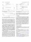
FIG. 7. Shot #105313: FRC phase and LID to cutoff. There is 0.68 μs displacement in the leading edge of the FRC between the two systems.
significant and provides a peak density fiducial. A CO2 inter- ferometer is 100 times less sensitive and appropriate for pick- ing up the phase trace beyond cutoff. The FRC velocity is ∼140 km/s, a lower bound, since the interferometers have dif- ferent impact parameters and the plasma edge depends on this. The lower FRC profile is shorter. The final system will have both CO2 and millimeter wave interferometers on a diameter chord.
The two discharges illustrate the phase performance of the system with regards to bandwidth. A measured phase changeof12000◦ in5μsfortheFRCis7MHz.Therun- ning phase signals must outrun any foreseen phase slew rates. An RF beat of 80 MHz and BW of 30 MHz are appropriate. The 30 MHz is set by the Nyquist frequency of the digitizer, 125 MHz, and the anti-aliasing filter which is 110 MHz. To accommodate more demanding applications with higher phase slew rates than shown in Fig. 7, the IF and bandwidth can be increased, for example, tripled to 240 and 90 MHz. This is the advantage of this technique.
Figure 8 shows shot #105298 which reaches cutoff slightly aftert=0withanLIDof1.2×1019 m−2 astheFRCmoves through the interferometer. A stable Jet plasma is established after a precursor density pulse with a stable period of 2.3 ms and then decays away coincidently with the termination of the FRC in the CV. The LID level correlates well with the CV mid- plane FIR chord LID at 5 ms when there is a uniform plasma density along the length of the vessel. The FRC’s radius, 40 cm, is given by the excluded flux radius plot of Fig. 8.
FIG.8. PhaseandLIDfortheJetplasmatogetherwiththeFRC’scentralLID and excluded-flux radius in the CV.
The vessel’s radius at the Jet interferometer is 35 cm, almost the same. So the LID in the Jet plasma is only 10 times lower than that of the FRC in the CV for this operational regime.
IV. SUMMARY
A two wavelength multi-chord tangentially viewing inter- ferometer system has been designed and partially completed to diagnose the density distribution of the C-2W plasma at the axial location of the magnetic mirror. The millimeter wave interferometer system has measured the FRC LID up to the 1021 m−3 cutoff and Jet plasma LID to be on the order of
−2
18
nosed with a millimeter wave system. The measured phase of
5 × 10
m
. The Jet plasma is sufficiently tenuous to be diag-
◦
the Jet plasma is ∼1000 which this system can resolve to a
∼1% accuracy. The FRC is overdense for the millimeter wave system confirming that a CO2 interferometer will provide com- plementary and complete measurements for full coverage of both FRC and Jet plasmas.
ACKNOWLEDGMENTS
We thank our shareholders for their support and trust and all fellow TAE staff for their dedication, excellent work, and extra efforts.
1M. M. Binderbauer et al., “A high performance field-reversed configura- tion,” Phys. Plasmas 22, 056110 (2015).
2H. Gota et al., “Achievement of field-reversed configuration plasma sustain- ment via 10 MW neutral-beam injection on the C-2U device,” Nucl. Fusion 57, 116021 (2017).
3M. Tuszewski, “Field reversed configurations,” Nucl. Fusion 28, 2033 (1988).
4I. H. Hutchinson, Principles of Plasma Diagnostics, 2nd ed. (Cambridge University Press, 2002).
5O. Gomostaeva, B. H. Deng, E. Garate, H. Gota, J. Kinley, J. Schroeder, and M. Tuszewski, “Two-color CO2/HeNe laser interferometer for C-2 experiment,” Rev. Sci. Instrum. 81, 10D516 (2010).
6 M. Beall, B. H. Deng, and H. Gota, “Improved density profile measurements in the C-2U advanced beam-driven Field-Reversed Configuration (FRC) plasmas,” Rev. Sci. Instrum. 87, 11E128 (2016).
