
Page 4 - Characterization and calibration of the Thomson scattering diagnostic suite for the C-2W field-reversed configuration experiment
P. 4
10C120-4
Ottaviano et al.
Rev. Sci. Instrum. 89, 10C120 (2018)
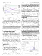
FIG.5. RelativesignalineachchannelfordifferentTe.
parameters for a typical unit: HV bias of 250–450 V, gain
of 50–100, quantum efficiency at 1060 nm of 40%, quantum
efficiency at 900 nm of 80%, and a noise enhancement factor
of 3–5. The detectors are water cooled to 20 ± 0.1 ◦C. The
avalanche photodiode (APD) connects to a second generation,
gated-integrator pre-amplifier based on the DIII-D Thomson
portion of the split light is coupled to a fiber and fed into a calibrated detector first then later switched to the input of the polychromator. By scanning and recording the reference detector energy and polychromator response, a trend of the polychromator throughput at each wavelength is recorded.
The spectral calibration uses the DC output channel of the polychromator since a DC source is used. The scalar cal- ibration from the AC/DC calibration is used to convert the polychromator DC output to the AC channel. Therefore, the spectral calibration result will have an absolute sensitivity of Rch(λi) for each spectral channel at each scanning wavelength as V/J. This sensitivity contributes to determine the TS sig- nal level in each spectral channel for a plasma with electron temperature Te and density Ne.
2. Calibration to reference detector and converting to power spectra
Once the monochromator (Acton model SP-2355) was calibrated, a broadband light source (Acton 30 W tungsten halogen) was used to determine the ratio of signals between an absolutely calibrated detector (ILT model ILT5000) and the reference detector (Keithley 6487 pA paired with Newport 818-SL) at wavelengths from 700 nm to 1100 nm. First, the responsivity for each detector was interpolated. Then the signal from the two detectors is acquired using the broadband CW light source over a range from 700 to 1100 nm in intervals of 0.5 nm, with 3 acquisitions per wavelength. The responsivity of each detector was applied at each data point to calculate the power for each wavelength.
Once the ratio of power spectra is obtained [expressed
as Rp(λi)], it is applied as a multiplier to each polychroma-
tor output (λi) to determine the power delivered from the
monochromator to the polychromator at each wavelength. The
spectral calibration results for a typical polychromator are dis-
played in Fig. 6 along with sample TS Te spectrum plots at
8
scattering system from 2009.
11
The system features a low
noise, high bandwidth transimpedance APD amplifier based
on the LMH6624 op-amp. The amplifier has two outputs, a DC
channel that directly outputs the APD photoelectron current
after being buffered and amplified and an AC channel which
is designed with background subtraction and an on-board gated
8
The gain of the AC and DC outputs of the electronic ampli-
fiers, together with the APD detector set with an appropriate
high voltage bias,8 is calibrated with the unit attached on a
water cooled mount. A laser diode is used as the source which
can be driven in pulse mode to simulate the laser pulse and
8
integration circuit for integrated scattering signal.
III. CALIBRATION AND PERFORMANCE A. Polychromator AC/DC calibration
in DC mode to generate uniform DC emission. The diode outputs when driven in AC/DC mode are monitored with an absolutely calibrated detector to quantify the input power to the APD unit. The energy per pulse can be obtained with the power and the driving frequency. The system DC response in V/W and the system AC response in V/J can be obtained. The scalar value between the two measurements is applied to the spectral calibration as the conversion between the DC measurement of the spectral calibration system and the AC response of the laser driven system.
B. Polychromator spectral calibration
The system is absolutely calibrated with Rayleigh scat- tering of argon gas. For the spherical molecular gas, e.g., argon gas, the Rayleigh scattering cross section can be derived with the classical models for radiation from an infinitesimally
FIG.6. Polychromatorchannelsignalsvs.wavelengthandexpectedscatter- ing spectrum using C2-W parameters for various Te.
varying Te (spectral calibration data provided by GA).
C. Rayleigh scattering calibration of the system
1. Spectral calibration system configuration
A spectral calibration is used to determine the absolute spectral response of each polychromator channel, which is used to resolve the Thomson scattering spectrum to deter- mine the electron temperature and density. A CW broadband light source is fed into a monochromator. The output of the monochromator is sent through a 50% beamsplitter with one side of the split light sent to a reference detector. The other
