
Page 5 - Characterization and calibration of the Thomson scattering diagnostic suite for the C-2W field-reversed configuration experiment
P. 5
10C120-5 Ottaviano et al.
Rev. Sci. Instrum. 89, 10C120 (2018)
small oscillating dipole p,12 which is induced by the incident laser field and is determined by the gas polarizability α as p = α E, in which E is laser incident field. The differential Rayleigh scattering cross section is
dσ π2α2 2
dΩ = ε2λ4 sin φ, (1)
0i
where φ is the angle of observation with respect to that dipole
◦ 12
vector, which is 90 in our experiment. The classical molec-
ular polarizability can be related to the index of refraction n by the Lorentz-Lorenz equation where α is the polarizability per particle independent of density,
α = 3ε0 n2 − 1 , N n2+2
where N is the number density of the gas. index of argon gas n can be obtained as
13
(2) The refractive
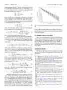
FIG.7. Centralregionpolychromatoroutputsforvaryingpressuresofargon gas.
leakage light through the baffle system. Further discussion on the calculation of Te and Ne can be found in the paper by Zhai
8 286.060 21 × 1012
(n−1)×10 =6432.135+
14.4 × 10⁹ − ν/cm−12 −1 13
, (3)
in these proceedings.
4
where ν is the wavenumber expressed in cm .
Comparison of the cross section of Rayleigh and Thomson
IV. SUMMARY AND FUTURE WORK
The central plane Thomson scattering system has been commissioned and calibrated on C-2W. Future work includes completing the jet TS diagnostic installation of C-2W, improv- ing the central diode-pumped laser’s energy stability to 2.0 J/pulse with <5% deviation and performing spectral cali- brations for the polychromators and AC/DC ratio calibrations for the APDs.
ACKNOWLEDGMENTS
We thank our shareholders for their support and trust and all fellow TAE staff for their dedication, excellent work, and extra efforts.
1M. W. Binderbauer et al., AIP Conf. Proc. 1721, 030003 (2016).
2M. C. Thompson, T. M. Schindler, R. Mendoza, H. Gota, S. Putvinski, M. W. Binderbauer, and TAE Team, Rev. Sci. Instrum. 89, 10K114 (2018).
3K. Zhai et al., in APS-DPP Conference Poster, 2016.
4K. Zhai, T. Schindler, A. Ottaviano, H. Zhang, D. Fallah, J. Wells, E. Parke,
M. C. Thompson, and TAE Team, “Thomson scattering systems on C-2W field-reversed configuration plasma experiment,” Rev. Sci. Instrum. (these proceedings).
5B. LeBlanc et al., in APS-DPP Conference Poster, 2017.
6J. A. Reusch, M. T. Borchardt, D. J. Den Hartog, A. F. Falkowski, D. J. Holly, R. O’Connell, and H. D. Stephens, Rev. Sci. Instrum. 79, 10E733
(2008).
7V. Ashoori, M. Shayganmanesh, and S. Radmard, in Heat Generation and
Removal in Solid State Lasers (InTech, 2012), Chap. 12, pp. 341–376. 8General Atomics Polychromator Systems User Manual Polychroma- tor Model GAPB-1064-IK-I Document 4-3248-3MAN, Revision A,
2017.
9EKSPLA ANL940 Laser Series, Technical Description Revision 1711,
2017.
10EKSPLA NL313 Laser Series, Technical Description Revision 1.1,
2017.
11T. M. Deterly, B. D. Bray, C. L. Hsieh, J. A. Kulchar, C. Liu, and
D. M. Ponce, IEEE Trans. Plasma Sci. 38(7), 1699 (2010).
12M. Born and E. Wolf, Principles of Optics Electromagnetic Theory of Prop- agation, Interference and Diffraction of Light (Cambridge University Press,
1980).
13M. Sneep and W. Ubachs, J. Quant. Spectrosc. Radiat. Transfer 92, 293
(2005).
scattering provides an estimate of the gas pressure necessary to generate a similar signal level as the TS signal level when
13 −3 ne ∼ 1 × 10 cm
. The scattering signal per channel can be
expressed as
Sts−ch =
where Sts (λi ) is the theoretical Thomson scattering power spec- trum, Rch(λi) is the spectral calibration system response at λi, and Fsystem is the system efficiency. The Rayleigh scattering signal can be expressed as
Sray = dσray Ngas L ∆Ω RRay−ch(λ0)E Fsystem, (5) dΩ
where σray is the Rayleigh scattering cross section, RRay-ch(λo) is the spectral calibration system response at λ0, and Ngas
Sts(λi)Rch(λi)∆λs ∆Ω E L neFsystem, (4) i
is the number density of Ar. Solving Eq. (4) for F system
and
substituting into Eq. (5) gives S=S(λ)R(λ)esray,(6)
n ∆λ R
ts−ch ts i ch i dσray
i RRay−ch(λ0) dΩ
where Rray = SRay/Ngas is the Rayleigh scattering coefficient.
Solving Eq. (6) for ne gives
Sts−ch RRay−ch(λ0) dΩ
dσray ne=(S(λ)R(λ))∆λ*S . (7)
Ngas i ts i ch i s ray
Rayleigh scattering is also used to align the collection optics with the laser beam by scanning the collection optics positions to maximize the Rayleigh scattering signal level. Once the alignment for the collection optics is optimized, a series of acquisitions are made with decreasing pressures of argon gas from 5 to 0 Torr. The results of the pressure scan are shown in Fig. 7. The slope from Fig. 7 is used to determine the Rayleigh scattering coefficient Rray-ch. The low signal level at 0 cm−3 is a measure of the successful elimination of laser
