
Page 7 - Anatomy of a field-reversed configuration
P. 7
Physics of Plasmas ARTICLE
FIG. 6. Trapped flux dependence.
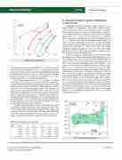
FIG. 7. R-Z distribution of traditional FRCs.
scitation.org/journal/php
relative fractions in the core and periphery. Table III shows the recon- structed values for the examples in Table II. Consider first the plasma energy. Three values are shown. The first is the standard formula based on excluded flux data, Ep0 [see Eq. (2)], which purports to represent the plasma energy in the core. Also shown are values for Epcore 1⁄4 core- proper energy, and Eptot 1⁄4 total of core and periphery.
Three interpretations from Table III are notable. (1) Plasma energy. The core energy Epcore is about 70% of the formula at larger radii and fractionally somewhat lower for smaller radius. (2) The total plasma energy Eptot is about a factor of 3.5 higher than the core. Thus, more than 3/4 of the plasma energy resides in the periphery. (2) Plasma current. Only a modest fraction, less than 30%, of the current flows inside the separatrix. In part the large energy and current frac- tions in the periphery arise because it is relatively long compared to the separatrix: the periphery half-length 1⁄4 2.9 m while the typical sep- aratrix half-length 1⁄4 1.1 m. (3) Rotation effect. The third observation is the importance of rotation, which reduces the core energy and current by about 30% relative to the non-rotating case.
Evidently the periphery plays an important role in modern FRCs accounting for a large majority of the plasma energy and current. This contrasts sharply with toroidal plasmas in general where energies, and currents are heavily dominated by the closed-field region. Moreover, in the FRC context, the standard formulas, e.g., Eqs. (1) and (2), are
IV. RECONSTRUCTION OF SPECIFIC EXPERIMENTS A. Shape domain
Grushenka reconstructs equilibria using “snapshot” inputs drawn directly from experiment. This section examines experi- mental results in the context of reconstructed properties. Consider first the shape domain in traditional h-pinch FRCs. A database22 listed snapshot properties of these once the formation dynamics had decayed. Figure 7 shows the R-Z distribution of traditional FRCs. Also shown is the relevant shape domain (shaded green) as in Fig. 4. Most data fall within the computed shape domain. Five points from TRX-2 with radii well above the common radius band are an exception. These differences may be resolved by suitable adjustment of field index or other factors. Note that TRX-2 employed a segmented magnet coil which may have affected the field index Nf and R/. These points also differ markedly from the data range from many other experiments.
With few exceptions, traditional FRCs were limited to stable lifetimes less than 100 ls and published results typically report sin- gle, “snapshot values” of R/, Z/ as well as other measurements. By contrast modern, beam-driven FRCs have many-millisecond life- times. From such data, Grushenka yields a full “timeline,” i.e., a sequence of reconstructed equilibria spanning the lifetime of the plasma. Figure 8 shows the shape trajectories, the R/ vs Z/ path, from several experiments over the plasma lifetime. Shown are shot 43628 from C-2U and shots 113301 and 113349 from C-2W. The dotted lines mark the upper and lower bounds of the radius band assuming rotation X 1⁄4 XJ. and field index Nf 1⁄4 0.1. The R-Z trajec- tories “move” within or very close to the radius band. Observe that the trajectories, which start at longer lengths (on the right) in Fig. 8, tend to hug the upper radius boundary. In the C-2W exam- ples, excursions toward lower radii (which has lower trapped flux) are temporary and the plasma “bounces” back up near the top. The fact that the R/-Z/ trajectories “travel” within the computed shape domain is circumstantial evidence that this is an actual “operational boundary.”
27, 112508-7
based on estimates that neglect the periphery. This is hardly
TABLE III. Plasma energy (kJ) and current (MJ).
the case.
Itot
0.633 0.429 0.705 0.314
X/XJ R/ (m) 1 0.450
1 0.360 0 0.470 0 0.265
Ep0 Epcore Eptot Icore 4.94 3.53 9.13 0.175
2.50 1.07 4.90 0.023 5.74 4.85 11.1 0.246 1.17 1.00 2.72 0.045
Phys. Plasmas 27, 112508 (2020); doi: 10.1063/5.0022663 Published under license by AIP Publishing
