
Page 12 - Demo
P. 12
042504-12
Rath et al.
Phys. Plasmas 24, 042504 (2017)
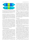
FIG. 17. Currents induced by axial displacement in a perfectly axisymmetric (upper) and more realistic, 3-D vacuum chamber (lower). Cell colors indi- cate the magnitude and direction of the resulting normal field, and arrows indicate direction and magnitude (color) of the current in the wall at a point. Even though the characteristic L/R time is 2.4 ms in both cases, the 3-D fea- tures reduce the instability growth time from 329 ls to 192 ls.
profound. Figure 17 compares the current patterns that are induced by an axial displacement in an axisymmetric vac- uum chamber with the patterns induced in a more realistic, non-axisymmetric chamber with otherwise identical thick- ness and resistivity. The color of the mesh elements indicates the magnitude and direction of the resulting normal field and the arrows the magnitude and direction of the current flowing in the wall.
The two walls have similar characteristic L/R times; in both cases, the slowest eigenmode decays with a time con- stant of 2.4 ms. However, the growth time of the axial stabil- ity changes from 329 ls (axisymmetric wall) to 192 ls. This is because the 3-D model has features that impair the current flow in exactly the area where most of the stabilizing cur- rents are induced. This difference is not visible in the L/R time of the wall because the eigenmodes simply shift to a different location. If the ports are modeled as simple cutouts with no nipples (not shown), the instability growth time reduces down to 44ls, i.e., there is almost no stabilizing effect from the wall at all. This was particularly important in our design work because of the large cut-outs required for neutral beams in the C-2W vacuum chamber.
C. Experimental implications
As mentioned in the introduction, the primary use of the model presented in this paper was the derivation of hardware requirements for the feedback control system of the C-2W device. For the specific plasma equilibrium discussed in this paper, the chosen hardware configuration was sufficient to control the positional instability for displacements of up to 20 cm with a considerable margin. Some of this margin will be required to compensate for the effects of using physical diagnostics instead of direct “measurements” of the plasma position, but on the other hand, control performance is also expected to improve when using a more sophisticated and optimized control algorithm in the final system.
Looking at the effects of increased control cycle time and latency, we found that an increase in latency has a much smaller performance impact than an increase in the cycle time. For example, the control performance with a cycle time of 60 ls and a single cycle (i.e., 60 ls) latency is much
worse than that with a cycle time of 10 ls but the same 60 ls latency (now corresponding to 6 cycles). In other words, even when discretized to steps of 400 V, the smoothness of the actuator commands matters. It is more important to update the actuator setpoints frequently than to minimize the relative age of the measurements that are used to calculate the setpoint. For this reason, the C-2W control hardware was designed to support sampling frequencies of up to 100 kHz together with deep pipelines. By pipelining, the control sys- tem will be able to accommodate a wide range of potential control algorithm execution times by varying the control sys- tem latency but without compromising on the sampling frequency.
Finally, we note that the same control algorithm was able to control the instabilities under a wide range of condi- tions, including cases with wall resistivity (and thus instabil- ity growth time) scaled by a factor of two and different unperturbed equilibria (not shown in detail in this paper). Given that the control algorithm contains no parameters that were derived from the plasma equilibrium, there is thus a good chance that the control of the plasma position will not require any additional input from a (slower running) equilib- rium reconstruction algorithm.
D. Future work
By using the uncontrolled growth rate of the axial insta- bility to fix the free parameter of the linear model, we have obtained a model that is sufficiently accurate to estimate the hardware requirements and controller performance for con- trolling axial plasma displacements. Since this model also includes the dynamics of the transverse plasma position, it is tempting to assume that it can be used for the design of a transverse position controller as well. This is probably the case, but there are two caveats.
First, it is not clear if the correct rigid volume for model- ing an axial displacement is necessarily also the right volume for modeling a transverse displacement.
Second, there is no direct evidence that the interpreta- tion of the free parameter as the rigidly moving part of the plasma is physically correct. This is because mathematically, the choice of the rigid volume amounts to a scaling of the instability drive by defining an effective toroidal plasma cur- rent (which linearly affects the driving force and quadrati- cally affects the restoring force). Therefore, it is possible to derive the same mathematical model by assuming a very dif- ferent rigid volume, instead postulating the existence of an additional energy sink (e.g., by the displacement causing additional heating) that brings the effective instability drive to the same level. This does not affect the practical useful- ness of the model. However, if we assume that our validation of the linear model (which was done by comparing axial position dynamics) also extends to its predictions for trans- verse displacements, then we imply that the rigid volumes (or the equivalent energy dissipation mechanisms) are the same for both dimensions. This is a plausible assumption too, but there is no direct evidence for it.
A valuable follow-up to the work presented here would thus be to compare the predictions of the linear model for
