
Page 3 - Rotational stability a long field-reversed configuration
P. 3
032507-3 Rahman et al.
cause the rotation velocity to decrease and the currents to
change.
III. HYBRID SIMULATIONS
The simulation considers the acceleration, formation, equilibration, and decay of a FRC plasma, using a modified version of the 2-1/2 D, time-dependent, MACH2 MHD code.15,16 A 2-1/2 D code has a two-dimensional grid, but computes all three components of the vector fields, for the velocity and magnetic field.
MACH2 is an Arbitrary Lagrangian Eulerian (ALE) code that solves for the continuity, momentum, energy, and mag- netic field equations on a grid composed of quadrilateral cells in the r and z plane. In the azimuthal direction, it solves the ion equation of motion. The code uses a finite volume differ- encing technique, and either analytic models or tabular values (SESAME tables at Los Alamos National Laboratory), for the equation-of-state and transport variables. In modeling the for- mation of a rotating FRC, when the plasma is optically thin, a simple radiation emission model employing non-LTE (non- local thermodynamic equilibrium) opacities was used.
Our interest is to account for observations in the Flux- Coil FRC (FC-FRC) experiments at UCI and Tri Alpha Energy, Inc. The experimental geometry is cylindrical, with plasma injectors located on both ends of the central- confinement region, an outer (flux-conserving) limiter coil, and a central flux-coil; both are pulsed LC circuits. The injected plasma is accelerated into the confinement section prior to FRC formation.
Published reports indicate an azimuthal-ion flow of vih 7 105 cm=s, measured by Doppler spectroscopy of impurities.8–10 In the FC-FRC Experiment, a 50G axial- magnetic field is applied, prior to formation, by first pulsing the Limiter Coil. The azimuthal-electric field is then generated by pulsing the Flux Coil, which results in a diamagnetic- plasma current that reverses the applied-magnetic field, inside the plasma-inner radius.
The azimuthal, electric-field generator was modeled by an equivalent solenoid circuit, connected to the coaxial-flux coil, for actual parameters from the experiment. The circuit-series resistance was 0.05 X with a coil radius of 10 cm and 14 turns connected to a capacitor of 1.25 mFd, charged to voltage of 3.5 kV. The quarter-period rise time of the flux-coil current is 100 ls with a maximum current of 48 kA. The background-magnetic field provided by the lim- iter coil is held fixed at 100 G. The radial scale for the simu- lation is Dr 1⁄4 10 30 cm and for the axial scale is Dz 1⁄4 690 cm. The simulation grid is comprised of 128 64 cells and the initial (start-up) plasma density and tempera- ture are n0 1⁄42 1013 cm 3 and T0 1⁄42eV.
The modified MACH2 code solves the hybrid set of equations described in Ref. 15 and including Eq. (11). Assuming x Xi, Eq. (11) simplifies to
Phys. Plasmas 21, 032507 (2014) Eh 1⁄4 1 @UBZ ; (21)
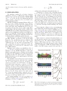
and UBZ is the axial-magnetic flux inside the flux coil. Normalized r-z contours for the total-plasma pressure, P 1⁄4 Pi þ Pe and vector-magnetic field, are plotted on the left side of Figure 2 at three time steps: t 1⁄4 50, 100, and 150 ls. The color bar at the top of each subfigure is for the pressure. At 50 ls, the plasma already exists as a high-pressure cavity, embedded in closed-magnetic-field lines, with an approxi- mate axial length, 630 cm. At the next two time steps, the length of the high-pressure cavity has decreased to 610 cm even as the length of the closed-field region has lengthened to 650–60 cm, reflecting an axial broadening of the current
layer.
On the right side of Figure 2 is the corresponding mid-
plane radial profiles, measured along the radius at z 1⁄4 0. The shape of these profiles agrees with the 1-D RRM predictions, cf. Eqs. (18) and (19). Some radial broadening of the profiles appears after 100ls, which is due to an expansion of the current-layer distribution, a general loss of confinement, and a decay in the plasma, as indicated by the decreasing null radius.
Figure 3 shows r-z contours for the plasma density, ni, at 50, 100, and 150 ls, plotted on the left side and mid-plane ra- dial profiles for ni(r). The compressional phase and the for- mation of FRC plasma lasts up to 50ls. After that the equilibrium phase starts when the plasma remains confined in the closed field lines of FRC. The plasma density at the middle of the FRC remains constant at the peak value of
FIG. 2. The left side displays r-z contours for total pressure and magnetic field (vectors), at 50, 100, and 150 ls. The right side displays normalized- radial profiles for the total pressure and axial component of the magnetic field, along the mid-plane, z 1⁄4 0.
2pr @t
dvih 1⁄4 e Eh ðge=miÞJh; dt mi
where Eh is calculated from Faraday’s Law
(20)
