
Page 2 - Inference of field reversed configuration topology and dynamics during Alfvenic transients
P. 2
ARTICLE
NATURE COMMUNICATIONS | DOI: 10.1038/s41467-018-03110-5
Afield reversed configuration (FRC) has no externally imposed toroidal field, belonging to the category of
inference technique. When Lorentz forces are balanced by plasma pressure, there is no net acceleration of the plasma, and the plasma is said to be in equilibrium. The determination of the magnetic structure corresponding to plasma in equilibrium is referred to in the literature as 'equilibrium reconstruction'.
This work departs from the standard equilibrium reconstruc- tion approach10 and use instead the current tomography (CT) method11, 12, a well-validated alternative already studied in con- nection with real-time control of tokamaks13. The CT method uses Bayesian inference14 of Gaussian processes (GPs)15 to solve the inverse problem. The GP modelling used by the CT method can be tailored to a multiplicity of related tomography pro- blems16, in particular to the specifics of the FRC magnetics. There are several advantages of the CT method that make it ideal for plasma control. First of all, when the relationship between current sources and sensors is linear (such as is the case with magnetic probes), and the physics assumptions can be reduced to linear relationships among current sources and measurements, the solution depends on the sensor data through non-iterative matrix operations and, for this reason, is deterministic and suitable for real time. A version of the algorithm for C-2W device has already been implemented in a field-programmable gate array and ver- ified to run under 10 μs. Second, as no equilibrium restrictions are necessarily required, the CT method can infer Alfvenic oscilla- tions from magnetic sensor data. Fast transients can then be resolved accurately and with very low latency, both factors known to have an impact on control systems performance. Third, the CT method is able to fuse information from multiple sensor data sets and boundary conditions using a unified inference approach. This allows straightforward scalability should other magnetic sensors become available at a later stage. Sensors based on Polarimetry17 and Hanle effect18, for instance, are both planned for TAE’s C- 2W device. Finally, the CT method provides uncertainty mea- sures on all inferred outputs. This is interesting information on its own, but it has also an interest for advanced control applications, since the uncertainty information can be factored in as part of a robust control scheme19.
Results
Inference of Alfvenic transients in FRC. In the C-2U device3, two individual toroidal current rings are produced inductively (θ- pinch technique) in two opposing quartz formation sections placed at both ends of a stainless steel vacuum vessel (Fig. 2). These are produced simultaneously using pulsed power, fast magnetic field transients, and then accelerated out of their respective formation sections at supersonic speeds vz ~ 300 km/s. Collisions of both FRCs take place inside the confinement vessel near or at the mid-plane z = 0.
The merging process occurs during the first few 10s of μs of the discharge, transforming the kinetic energy of the two initial compact tori into thermal energy of a single, static FRC20. Neutral beam heating is then applied to this initial FRC to provide the necessary heating and current drive to sustain the discharge against thermal and resistive flux losses.
When the accelerations in both formation sections are slightly different with respect to each other, FRCs do not collide exactly in the middle of the confinement section, leading to a merged FRC with a residual velocity. The resulting FRC is bounced back and forth in the axially stabilizing external mirror field until its position is stabilized around the machine mid-plane. Analysis of these oscillations provides a way to test the compliance of the inferred forces and accelerations with Newton’s second law, using estimations of the plasma mass obtained by other diagnostics, as it will be shown.
1, 2
compact tori . The poloidal field in an FRC has one
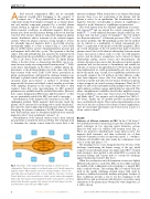
component arising from magnets arranged on a common linear axis and another component generated by a toroidal plasma current flowing in opposite direction to the magnet currents. Under transient conditions, an additional magnetic field com- ponent arises from toroidal currents flowing in the vessel (the flux conserver (FC) current), which are induced by changes in plasma current distribution and/or transients in the external magnet currents. When the plasma current is strong enough to reverse the externally imposed magnetic field, a closed field structure topologically similar to a torus is formed (Fig. 1). Closed field lines in an FRC enclose a point of maximum kinetic pressure and null magnetic field called the o-point. The separatrix is the flux surface with null poloidal flux and separates the internal closed field region from the open field line scrape-off layer (SOL) region.
The C-2U device, built and operated by Tri Alpha Energy (TAE), is the first device to demonstrate that FRCs can be sus- tained in near steady state using neutral beam injection3, 4. TAE’s C-2U device relied largely on FC effects to stabilize plasma dis- placements, so the discharge lifetime was of the same order as the time constant of the vessel. TAE’s C-2W device, presently in its initial operational phase, will extend the discharge duration over this limit, so plasma control will become necessary to stabilize the separatrix shape and position5. A method to determine the magnetic field structure and related control variables in real time (with sampling frequency in the range 10–100 kHz) is then required. Some first order approximations for FRC geometry parameters are available from the excluded flux radius. However, these cannot distinguish an FRC from a high beta mirror6, so they are not particularly useful if the FRC state itself is uncertain.
Determination of the magnetic field structure in an FRC is a challenging problem. While magnetic field structure inside the plasma can be measured by inserting probes inside the plasma7, this cannot be done in high temperature plasmas without severely disrupting the plasma confinement. In FRC plasmas, the mag- netic field structure must be determined indirectly from external magnetic probes8, laser polarimetry systems9, etc.
Determination of the internal current sources from external measurements is termed the inverse problem. The technique used to determine the current sources from the sensor data is the
Fig. 1 Schematics of the magnetic field topology in a field reversed configuration. Plasma (orange) is contained using a set of axially symmetric magnets (blue). When plasma current is strong enough to reverse the externally imposed magnetic field, a closed field line structure is formed. Closed field lines circle around the so called o-point, where the magnetic field is null. The longest closed magnetic field line enclosing the o-point has null poloidal flux and separates the internal closed field region from the open field line scrape-off layer (SOL) region
2 NATURE COMMUNICATIONS | (2018)9:691
| DOI: 10.1038/s41467-018-03110-5 | www.nature.com/naturecommunications
