
Page 3 - Inference of field reversed configuration topology and dynamics during Alfvenic transients
P. 3
NATURE COMMUNICATIONS | DOI: 10.1038/s41467-018-03110-5
ARTICLE
Formation section
t=8 μs 0.6
0.4
0.2
1.2
1.0
0.8
0.6
0.4
0.2
1.2
1.0
0.8
0.6
0.4
0.2
1.2
1.0
0.8
t=64 μs
Confinement section
Formation section
ne(1019 m–3) 21.0
20.4
19.9
19.3
18.7
18.2
17.6
17.0
16.5
1.2
1.0
0.8
0.6 0.4 0.2 1.2 1.0 0.8 0.6 0.4 0.2
t=128 μs
t=16 μs
t=32 μs
–6 –4 –2 0 2 4 6 Z (m)
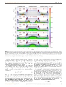
Fig. 2 MHD simulation of a typical FRC process in the C-2U device. Two FRCs are created in two quartz formation sections. They are accelerated towards each other to collide and merge into a single FRC inside a stainless steel confinement chamber. The collision transforms the kinetic energy of both moving FRCs into thermal energy of a single, static FRC. Magnetic field topology in the SOL (solid lines), closed field region (broken lines) and separatrix (thick solid line) are shown along with colour-coded electron density. DC Magnets (brown blocks), flux conserver structures (blue), fast switching magnets (dotted red line) and quartz tube boundaries (green horizontal lines) are also shown for completeness
A plasma discharge exhibiting Alfvenic plasma oscillations around the midplane is chosen for the study, as illustrated in Fig. 3. Contours of poloidal flux and forward prediction of the actual magnetic measurements are shown every 10μs. The frequency of the oscillations is about ~ 20 kHz.
The axial position of the o-point is shown in Fig. 4 with high time resolution (every 10μs), along with other geometric descriptors and plasma variables related to those. The o-point position is strongly correlated with the vessel current imbalance IVζ , defined as:
other half of the vessel with z < 0. For a static plasma, the vessel current imbalance is zero. As plasma moves back and forth, mid- plane antisymmetric current components are induced in the vacuum vessel, which eventually dissipate ohmically. These are in the direction to oppose and slow down the plasma movements.
As a result, a strong correlation between the o-point axial position and the vessel current imbalance exists, as shown.
The separatrix radius is found to be proportional to the o-point radius, which is in agreement with Eq. (7). The trapped flux ψ0 also matches approximately the approximation (9) for an elongated FRC. These approximations are not used in the inference process but as a check for consistency of the final results with these limiting cases.
The total number of deuterons in the plasma is estimated from
line integrated density measurements integrated over the
excluded flux radius. Plasma mass is estimated to be mp = 1.3 ×
10−7 kg from the deuteron mass times the deuteron inventory.
The acceleration €z of the o-point can be determined from its
position z (see Fig. 4). The net Lorentz force F exerted over the z
whole plasma current distribution can be determined from the inferred current distribution and derived magnetic field. It turns out the product of the plasma mass and acceleration €z is consistent with the inferred electromagnetic force
ζ z>0 z<0 IV1⁄4IV IV
ð1Þ where Iz>0 is the net toroidal current flowing in one half of the
V z<0
vessel with z > 0, and IV is the net toroidal current flowing the
F z 1⁄4 m p €z ð 2 Þ NATURE COMMUNICATIONS | (2018)9:691 | DOI: 10.1038/s41467-018-03110-5 | www.nature.com/naturecommunications 3
R (m) R (m) R (m) R (m) R (m)
