
Page 2 - EX_P3-37_a2
P. 2
2 EX/P3-37 tuned MCPG was mounted on the C-2U device and multiple injection and response of the
FRC has been evaluated.
2.1.Developed Plasma Gun
Figure 1 shows a schematic of the developed MCPG. It consists of a set of coaxial cylindrical electrodes, a bias coil and four gas injection ports which are arranged tangentially on the outer electrode. The inner electrode is coated by tungsten to reduce impurity influx. A plasma ring is generated within a gap between the electrodes and is accelerated by Lorenz self-force. During this acceleration process, toroidal current is induced by a poloidal flux interlinked with the plasma ring. Then, the magnetized spheromak-like CT is ejected from the MCPG.
FIG. 1. Schematic view of the developed CT injector.
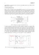
To refuel the particles of long-lived C-2U FRCs, multiple CT injections are required. Thus, we have developed the multi-stage discharge circuit as shown in FIG. 2 for multi-pulsed CT injection [5]. Drive frequency of this system can be adjusted up to 1 kHz and the number of CT shots per injector is 2; the system can be further upgraded for larger number of injection pulses. Table 1 lists the typical parameters of the generated CT on the test stand and the target of C-2U FRC. The developed MCPG has achieved supersonic ejection velocity in the range of ~100 km/s. Key plasma parameters of electron density, electron temperature and the number of particles are ~ 5 × 10²¹ m-3, 20 - 30 eV, and 0.5 - 1.0 × 10¹⁹, respectively.
FIG. 2. Schematic diagram of multi-pulse discharge circuit, which includes charging circuit, main bank, snubber circuit, and CT injector.
