
Page 4 - EX_P3-37_a2
P. 4
4 EX/P3-37
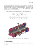
vicinity of midplane. CT injectors are oriented at an angle with respect to z-axis and both CT injector are installed 180 degrees apart, slightly off-axis, and angled such that the injected CTs’ trajectories intersect at the center of the confinement vessel. The CT injector 1 has multi-pulse system that can inject two CTs with repetition rate up to 1 kHz. Therefore, we can inject the 3 CTs in the configuration lifeime of the C-2U FRC. TABLE I lists the typical plasma parameter of C-2U FRC and a injected CT.
TABLE I: TYPICAL PLASMA PARAMETERS OF C-2U FRC AND INJECTED CTS.
Particles (×1019)
Temperature [eV]
Poloidal flux [mWb]
Energy [kJ]
FRC
1.0 – 1.5
600 – 800 (total)
5–7
5–7
CT
0.5 – 1.0
20 – 30 (electron)
0.4
0.1 – 0.3
FIG. 4. Schematic drawing of CT injector arrangement on the C-2U device.
3. Experimental Results
The specifications of ejected CTs had been examined and operations were optimized on the test stand. Then, single and double pulsed CT injection fueling have been conducted on the C- 2U facility.
