
Page 3 - EX_P3-37_a2
P. 3
3 EX/P3-37
To improve the performance of fueling by the MCPG, a pre-ionization (PI) technique has also been developed. This can decrease the trailing neutral gas from the CT injector which potentially cools the FRC plasma. The PI electrode is made of semi-rigid coaxial cable with Teflon insulator. The inner and outer electrodes are made of copper and the diameter of the outer electrode is 6.5 mm. The plasma discharge is initiated between electrodes on the end surface in the same way as a pulsed-plasma thruster (PPT). Then the plasma is accelerated by Lorentz self force and injected into the gap between coaxial electrodes. This reduces the amount of initial neutral gas required to initiate the breakdown of CT formation. Also the injected gas is more efficiently used to form the plasmoid. These reduce the inflow of trailing neutral gas into the main confinement vessel.
2.2.Test Stand
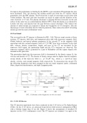
The test stand for the CT injector is illustrated in FIG. 3 [8]. This test stand consists of three sections: CT injector, drift tube, and transparent glass tube with transverse magnetic field. Global behavior and typical plasma parameters of the ejected CT in the magnetic field equivalent with the external magnetic field of C-2U FRC have been evaluated. In the drift tube, velocity, density, temperature, length, and mass of the CT are measured. In the transverse field region, the penetration depth and the CT’s trajectory are observed. The transverse magnetic field is generated by a pair of Helmholtz coil like square shaped coils mounted on the glass tube.
The penetration depth into the transverse field is determined by the kinetic energy Ek; the velocity and density of CT. The density of kinetic energy must be higher than the magnetic
energy density of the transverse field, i.e., ρv2 2 ≥ B2 / 2μ0 , where ρ, ν, and B are mass
density, velocity, and external magnetic field, respectively. To characterize the ejected CTs the following diagnostics had been arranged on the test stand: magnetic probe, collimated fibers, dispersion interferometer, and triple Langmuir probe.
FIG. 3. Schematic of the diagnostics on the test stand.
2.3. C-2/C-2U Device
The CT injection experiments have been conducted on the C-2U device at Tri Alpha Energy (TAE). On the C-2U device, an advanced beam-driven field-reversed configuration (FRC) with a lifetime longer than 10 ms [4]. Figure 4 shows the arrangement of installed CT injectors on the C-2U confinement vessel. The CT injectors are mounted 1 m apart in the
