
Page 2 - Fast-ion D-alpha diagnostic development for the C-2W field-reversed configuration plasma
P. 2
10D106-2 Bolte et al.
Rev. Sci. Instrum. 89, 10D106 (2018)
and the LOS intersect many different flux surfaces over a large volume. This may reduce the spatial resolution and make des- ignation of LOS with respect to flux surfaces less meaningful. This may be offset, however, if velocity-space tomography is carried out as the inferred distribution would more represent the global distribution and not just a localized one due to the large emitting volume.
II. SPECTROMETER DESIGN
FIDA spectra are generally low-level signals in fixed wavelength ranges. As shown in previous work,11,12 FIDA spectrometers are great candidates for using high-dispersion volume-phase holographic transmission gratings (VPH “grisms”). When paired with f/1.8 camera lenses, these grisms produce a high throughput fixed wavelength spectrograph like the Holospec spectrograph purchased from Kaiser Optical Systems, Inc. The purchased grism has a peak transmission at 656.0 nm and a transmission range of 635.7-673.1 nm. This exceeds the ∼13 nm required to measure emission from the up to 40 keV hydrogen neutrals from TAE’s planned switchable beams. In addition to the spectrograph shown in Fig. 1, the system will have a neutral density filter strip at the output focal plane to reduce the unshifted and cold D/H-alpha emission. A second pair of external camera lenses will be used to magnify the image onto the camera’s detector which is a complementary metal-oxide-semiconductor (CMOS) array.
The spectrograph has collimating and focusing lens foci of 75 and 85 mm, respectively, giving a magnification of 1.13. Using a slit width of 100 μm, the reciprocal linear dispersion at the external focal plane is 1.47 nm/mm, giving a width of 0.55 mm for the neutral density filter to block out 0.8 nm for the cold emission. Using 50 and 85 mm foci for the external lenses magnifies the image 1.7× before it reaches the camera CMOS array.
Details of the proposed measurements were calculated using Bell’s formalism11 along with basic optics and signal- to-noise ratio (SNR) methods.
In general, FIDA measurements must have a background subtraction method to remove passive light such as edge- neutral radiation and bremsstrahlung. The two methods typi- cally employed are beam modulation and direct measurement of the passive light. The latter option is not available in TAE’s FRC experiments as beam-free regions are not sufficiently
FIG. 1. Inside of spectrograph: 1—collimating lens, 2—transmission grat- ing/prism combination, 3—focusing lens.
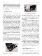
FIG.2. PhantomMiro110Lhigh-speedcamera.
large to permit such measurements. As such, all past and planned FIDA measurements utilize the modulation of heat- ing beams to obtain and remove the background signals. The “beam-on” signals discussed below include active and passive radiation while the “beam-off” signals only include passive background signals.
A spectrally averaged raw beam-off signal level of 3.1 × 10¹⁷ ph/(s-nm-m3-sr) was taken from C-2U measure- ments1 as a starting point. This was considered a good estimate of C-2W FIDA levels considering that C-2W has 30% more beam power and up to 2.7× the beam energy of C-2U. The rel- atively large expected FIDA signal allows for magnification onto the detector which reduces SNR but increases resolution. A Phantom Miro 110 camera (Fig. 2) was chosen for imaging spectra. The camera has a maximum frame-rate of 1600 fps at the full 1280 × 800 pixel resolution, which is more than enough for the 1-ms modulation time of TAE’s beams. Taking into account the second set of lenses, the reciprocal linear dis- persion is 0.86 nm/mm at the detector, giving a spectral width of 15.5 mm, or 60% of the Phantom’s 25.6 mm wide CMOS array. The system can then image up to eight 1-mm fibers, taking up 88% of the detector’s height. The dispersion and the Phantom’s quantum efficiency of 0.35 give a 1-ms integrated signal of 3.9 × 10⁹ e−/pixel, which is 15% of the full-well depth. With photon noise and the manufacturer-stated readout noise of 29 e− (dark current is negligible), the expected raw SNR is 56. C-2U measurements showed that beam-on signals were 32% higher than beam-off signals, giving an SNR of 12 for the FIDA contribution to the 4.1 × 10¹⁷ ph/(s-nm-m3-sr) beam-on signal.
The final spectrometer design is expected to have a spec- tral resolution of <0.2 nm (<50 eV full energy for protium). Up to eight LOSs are planned to view roughly perpendicu- lar to a single beam’s centerline, spaced 2 cm apart along the centerline. The time resolution is limited to the heating beam modulation frequency and therefore will be the same as the C-2U measurements of one net measurement every 2 ms.
III. SIGNAL COLLECTION AND NEUTRAL BEAM CONFIGURATION
The machine-side optics will consist of four to eight 1′′ diameter collimators on each of two ports. The mount will need to be axially tilted to track the beam center-lines which are tilted in the x-y and the y-z planes of the cylindrical vessel (see Fig. 3). One millimeter diameter 0.22 numerical aperture
