
Page 3 - Fast-ion D-alpha diagnostic development for the C-2W field-reversed configuration plasma
P. 3
10D106-3 Bolte et al.
Rev. Sci. Instrum. 89, 10D106 (2018)
FIG.3. CrosssectionoftheC-2WvesselemphasizingthechosenFIDAport and portion of neutral beam 1 expected to produce FIDA signals (shown in Fig. 6). Inset: End-on view showing beam layout, symmetry, and numbering.
fibers will be used throughout for maximum coupling to the Holospec spectrograph. The collimators will be connected to jumper fibers that will connect to the main fibers extending ∼35 m to the spectrometer. There they will connect to jumper fibers that are rigidly bound on a curve to match the curved entrance slit.
C-2W has 8 neutral beams (Fig. 3). Beams 1, 4, 5, and 8 are tilted 26◦ downward while beams 2, 3, 6, and 7 are tilted 26◦ upward. All beams are tilted 22◦ inward relative to the axis of the machine. The current can be modulated at 500 Hz at 50% duty cycle, giving 1-ms integration times for both FIDA signal and background. The beams are nominally 15 keV and 1.5 MW each. Switchable beams able to rise to 40 keV will soon replace four of the beams.
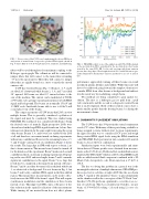
The compact geometry of C-2W means that LOS can view multiple beams. This is generally considered a pollution of the signal and must be considered. This was studied using FIDASIM. The north port was considered with beam 1 being the desired source of neutrals. Eight prospective LOSs were chosen based on the large FIDA signal from beam 1 alone. Sim- ulations were then run for the same eight views using the seven other beams. Beams 3, 4, and 6 were not visible by the LOS at all and therefore can remain turned on during experiments without any contribution. However, the remaining beams (2, 5, 7, and 8) make varying levels of contribution. Figure 4 shows the results. The large dips in SNR with respect to beam 2 are due to beam emission. This means beam 2 must be turned off for the duration of the experiment. Beam 5 makes such a small contribution that it can remain on during experiments. Depend- ing on the exact LOS and wavelength, beams 7 and 8 can make significant contributions to the signal. Beam 7 is so large that it will also be considered as the main beam instead of beam 1. Beams 7 and 8 can either be turned off, modulated with beam 1, or subtracted as background. It is not shown in Fig. 4, but beams 7 and 8 only contribute FIDA signal in the blue-shifted region. This means these measurements can be used to effec- tively increase the SNR of the beam 1 signal. This will require synchronous modulation and the simulation of three beams instead of one. This improved SNR comes at the price of fur- ther reduction in the spatial localization of the measurement. While turning off one neutral beam does not affect plasma
FIG.4. FIDASIMresultsforoneoftheeightproposedLOSs.SNRisdefined as the spectrum from NB 1 normalized by the spectrum from other beams viewed by the same LOS. NB 2 is the only spectrum with beam emission present (three large dips). Wavelengths between 654.5 and 656.0 nm are gen- erally dominated by thermal halo emission and therefore are not of interest here.
performance appreciably, turning off three beams can result in reduced plasma lifetime and stability. While this issue will have to be addressed going forward, the simplest solution is to consider FIDA from other beams as background and subtract it in the usual way by modulating a single beam.
Two methods are being considered to gain spatial res- olution. The first is a hydrogen gas jet puff from a puff valve and nozzle and the second is a diagnostic neutral beam that is in development. Both of these neutral sources have a much smaller profile than the heating beams, localizing the measurement volume.
IV. DIAGNOSTIC PLACEMENT SIMULATIONS
The C-2W device has 354 ports in the central confinement vessel (CV) alone. With many of these ports being available or being assigned to items without strict location requirements, the approach taken was to consider all CV ports and weigh their potential FIDA signal levels using the FIDA simulation code FIDASIM. Each port must in turn consider all 8 neutral beams to choose the best combination.
Simulation inputs were both experimentally and simu- lation derived. Plasma profiles were obtained from measure- ments on the C-2U device. Fields and fast-ion distribution were simulated by TAE’s Q2D2 which is a 2D two-fluid MHD model with an added neutral fluid component combined with a 3D Monte Carlo fast-particle code. Beam injection is 15 keV at 130 A.
The key to solving this problem in a general way is the meaningful reduction of multiple dimensions. FIDASIM pro- duces spectra for each line-of-sight (LOS) like the one shown in Fig. 5. A grid of 182 simulated “lenses” is placed uniformly on the chamber wall in the core region of the CV. Each “lens” then has 195 LOSs per beam, optimized to cover the cross sec- tion of each beam. This was calculated in 8 batches, one per beam, of 35 490 LOSs, taking ∼2 h each using 12 cores of a cluster.
