
Page 4 - Fast-ion D-alpha diagnostic development for the C-2W field-reversed configuration plasma
P. 4
10D106-4 Bolte et al.
Rev. Sci. Instrum. 89, 10D106 (2018)
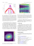
FIG. 5. Sample FIDASIM output for a single line-of-sight showing D-alpha light emission from various sources of neutral gas. While bremsstrahlung is removed by background subtraction, it reduces raw SNR and so its low level is shown for reference. The three narrowest features are emission from the three energies of beam neutrals themselves. The medium-width structure is the emission from the so-called “halo” which is a population of neutrals resulting from thermal ions undergoing multiple charge exchange events with beam and halo neutrals. The broad FIDA feature is the emission from fast neutrals after fast ions charge exchange with either beam or halo neutrals. This LOS is largely perpendicular to the beam as can be seen by the small shift in the beam emission from the unshifted wavelength of 656.1 nm.
The spectral information needed to be reduced down to only “useful” FIDA signals. To this end, usable FIDA spectra were defined as being blue-shifted and having and a SNR of at least 2 compared to the non-FIDA contributions (beam, halo, bremsstrahlung). Regions of the desired blue-shifted portion of spectra with poor FIDA-to-non-FIDA SNR or where beam emission is blue-shifted are set to zero for each LOS. Each spectrum is then integrated over wavelength, creating a FIDA- like contour for each beam as seen in Fig. 6. Taking the sum over beam-space of the FIDA-like contour gives a single value
FIG.7. SamplecontourofnettotalFIDAforbeam1inmachinecoordinates. Ports are shown as diamonds. The circled port is the one chosen for FIDA spectra measurements due to its large signal and availability. The beam cen- terline is in red, entering the chamber at the O and hitting the opposite wall at X. The amplitude can be interpreted as the total blue-shifted FIDA signal with acceptable SNR (>2× non-FIDA emission) for the given beam if many lines-of-sight emanated from a given point on the contour.
for each lens for the total FIDA signal if that location were used to thoroughly image a given beam. A contour like Fig. 7 can then be made in machine coordinates to indicate the integrated FIDA signal for anywhere in the CV.
V. CONCLUSION
A spectrograph and camera were purchased for TAE’s new FIDA spectrometer. Ideal available ports were chosen using FIDASIM. Design work has begun for the entrance slit, machine-side optics mount, and ancillary components. The first FIDA spectra will be taken on C-2W in the upcom- ing 2018-2019 campaigns. Several challenges will need to be addressed going forward such as the issue of viewing multi- ple beams and whether velocity-space tomography is possible or whether a more integrated Bayesian method is required for inferring the fast-ion distribution function.
ACKNOWLEDGMENTS
We thank our shareholders for their support and trust and all fellow TAE staff for their dedication, excellent work, and extra efforts.
1N. Bolte, Rev. Sci. Instrum. 87, 11E520 (2016).
2M. Onofri, Phys. Plasmas 24, 092518 (2017).
3See http://d3denergetic.github.io/FIDASIM/ for FIDASIM code and code
documentation.
4W. Heidbrink, Commun. Comput. Phys. 10, 716 (2011).
5B. Geiger, “Fast-ion transport studies using FIDA spectroscopy at the
ASDEX Upgrade tokamak,” Ph.D. thesis, Ludwig Maximilian University
of Munich, 2012.
6M. Binderbauer et al., AIP Conf. Proc. 1721, 030003 (2016). 7W. Heidbrink, Rev. Sci. Instrum. 81, 10D727 (2010).
8N. Bolte, Nucl. Fusion 56, 112023 (2016).
9M. Podesta, Rev. Sci. Instrum. 79, 10E521 (2008).
10M. Salewski, Nucl. Fusion 53, 063019 (2013).
11R. Bell, Rev. Sci. Instrum. 75, 4158 (2004).
12A. Bortolon, Rev. Sci. Instrum. 81, 10D728 (2010).
FIG. 6. Sample contour of FIDA-only spectrally integrated simulated emis- sion for neutral beam 1, viewed from port CV066N346.
