
Page 2 - Magnetic diagnostic suite of the C-2W field-reversed configuration experiment
P. 2
10J107-2 Roche et al.
Rev. Sci. Instrum. 89, 10J107 (2018)
TABLE I. Details of probe installations: locations, types, and primary measurements.
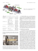
FIG. 1. Overview of C-2W and magnetic field probe installation locations (highlighted in green).
Two additional Mirnov arrays are installed in the inner divertors. They detect the initial translation of the FRC and can diagnose fluctuations in the FRC exhaust. These probes, including wiring, are completely internal to the vacuum vessel. All 8 probes of each ring exit the vessel through a single feed- through.
In addition to the 64 probes of the Mirnov array, there is another array of probes that, with a few exceptions, is laid out in an axially linear pattern along the CV. This array consists of 22 probes in total. Only Bz is digitized for these probes. However, there is an additional measurement of Bz , taken just outside the vacuum boundary, which allows us to characterize the decay of eddy currents in the vessel wall generated inductively by the FRC’s plasma current. In fact, every magnetic probe has an external Bz measurement just outside the vessel connected to the vacuum interface; this interface is described in Sec. III.
B. Total flux and average B-field
It is advantageous to know the total magnetic flux and average magnetic field just inside the CV’s wall. These mea- surements allow us to calculate the FRC’s excluded flux radius.6 To make this measurement, 3 wires at minimum must be affixed to the vessel wall at the same axial position and slightly different radial positions (see Fig. 3). Consistency of the spacing between wires is essential as the sensitivity of the probe to the magnetic field at any given azimuth is determined by the distance between them. Any deviations distort the aver- age by weighting the field differently at those points where the deviations occur. The probe must also be resilient enough to survive in a hot plasma environment as well as be compatible with an ultra-high vacuum (UHV) system. Development of a suitable diagnostic was a joint effort between ARi Industries and TAE Technologies, Inc. The probe consists of 3 copper wires arranged vertically inside of an oval shaped stainless steel jacket (see Fig. 3) that is packed tightly with magnesium oxide, a dry insulating powder, commonly referred to as Min- eral Insulation (MI). The jacket must be very thin as to preserve frequency response, and so the wires can be easily formed to the shape of the vessel. The probe’s B-dot signal was found to have a flat frequency response up to 50 kHz. The oval shape of the probe allows the orientation of the internal wires to be correctly aligned. The two outer wires are shorted on one end to form the local, azimuthally averaged B-dot probe, and the
Location
Confinement vessel
Inner divertors
Formation section Outer divertors
Diagnostic type
In-vacuum B-dot/flux loop (22)
Linear array (22 Bz) Mirnov array of 64 probes B,δB
External array (108 Bz) In-vacuum Rogowski (2) External flux loops (48)
In-vacuum B-dot/flux loop (6) Mirnov array of 16 probes B
Flux loops (34) In-vacuum Rogowski (2)
Measurement Excluded flux
Excluded flux Plasma motion and fluctuations Flux leakage Plasma current External flux
Excluded flux FRC translation FRC translation jet dynamics
FRC formation FRC translation Plasma current
64 probes or 384 signals. Spectral analysis of the signals reveals both spatially coherent and incoherent fluctuations in broadband.
FIG.2. PartiallyassembledpointB-fieldprobewithsensoraxeslabeled.Vac- uum interface also shown. Complete probe has a metallic structure that is flush with the CV wall and a quartz tube that covers and protects the exposed ∼1 cm from the plasma. On each plane of the probe, the 2 chips measure the fluctuations of the magnetic field with sensitivity to high and low frequencies.
