
Page 3 - Magnetic diagnostic suite of the C-2W field-reversed configuration experiment
P. 3
10J107-3
Roche et al.
Rev. Sci. Instrum. 89, 10J107 (2018)
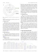
FIG. 3. (a) Schematic of 3 wire probe loops. (b) Cross-sectional view of 3 wire probes.
third wire is used to measure the total flux exactly at the center of the B-dot measurement.
C. Plasma current
Measurements of plasma current flowing axially through- out the vacuum vessel can provide essential information about flows and edge biasing effectiveness. Similar to the 3 wire probe described in Sec. II B, an MI cable with a Rogowski coil7 inside, also developed by ARi Industries, is used to make this measurement. The probe consists of a copper wire that has been wound into a spiral along the inside of the stainless steel jacket. A return wire is threaded through the spiral. On one end, the return wire is shorted to the spiral wire and two leads exit the vacuum vessel in the same manner as the probes detailed in Sec. II B.
D. External flux loops
Due to the eddy currents flowing in the vessel wall, it is also important to measure the total flux on the air side. To accomplish this requirement, many flux loops are posi- tioned on and around the vessel, as described in Secs. II D 1 and II D 2.
1. Formation section
C-2W has two precisely timed formation sections where FRCs are generated and accelerated via a staged theta pinch.
Each of the 17 coils is fired in rapid succession in an attempt to trap flux and push the plasma, with peristaltic motion, through the inner-divertor and into the CV where the two FRCs col- lide and thermalize. To measure this process in the formation section, flux loops are installed directly beneath each of the 17 coils on each side. They measure both the field due to coils and the plasma’s response in superposition.
The flux loops themselves are constructed out of resistive Nichrome wire. A voltage divider is also incorporated into the diagnostics as the loop voltages can exceed 40 kV. The signals are integrated using passive RC integrators and digitized with fast cards at 80 MS/s.
2. Confinement vessel
There are also several flux loops that encircle the entire vessel. There are 8 loops that are constructed out of layers of Kapton® tape and copper tape. These loops are affixed to the ID of each of the 8 equilibrium magnets. There are 4 more loops that are simply wrapped around the OD of the CV. These loops are just simple wires. Loop voltages are much smaller (∼80 V) in this area, so no special precautions are required. However, the signals are divided down so that they conform to the input voltage range of the active integrators and associated digitizers.
To provide axial stability to the FRC during plasma shots, 32 saddle coils are installed around the CV. There are 2 layers and 4 rows of 4 of these saddle coils. Each saddle coil has 2 flux loops wound along its inner perimeter for redundancy. The flux loops measure the radial flux generated by each of the saddle coils. This information will be used for active feedback stabilization of the plasma.
III. DATA FLOW AND ACQUISITION
Data acquisition of these signals requires a significant amount of planning. A map is built up of the entire sys- tem which can be accessed visually or programmatically. An example map for a single Mirnov probe is depicted in Fig. 4. Similar paths exist for each diagnostic. Almost all of the inter- nal magnetic probe signals have a standard vacuum interface, Accu-Glass Products, Inc., part number: 110210, which con- tains a MIL-C 26482 19-pin interface. On the air side of each of these feed-throughs is a custom circuit board that inter- faces with the MIL-C connector; is an onboard chip inductor which is aligned with the axis of the machine, making it
FIG.4. SignalpathforoneoftheMirnovprobes,fromtheprobetothedigitizer,withatotalof6signals.Suchagraphexistsforeachofthe700+signals.
