
Page 4 - Magnetic diagnostic suite of the C-2W field-reversed configuration experiment
P. 4
10J107-4
Roche et al.
Rev. Sci. Instrum. 89, 10J107 (2018) The resulting solution for r∆Φ is
r∆Φ = rl 1 − Φp Bv , (2) Φv Bp
where v stands for vacuum and p for plasma. All measurements are taken at rl.
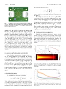
The multiple measurements of Bz and Φ along the C-2W’s vessel wall allow us to determine this quantity for the entire plasma column. This quantity is a good approximation for the separatrix radius of an FRC. In order to limit the need for a vacuum shot for each plasma shot, a curve is fit to both the flux and field excluding the time when plasma is present to provide an equivalent to the vacuum case. The “plasma time” is set to slightly longer than the time neutral beam injection is operational. Then the resulting traces are used to calculate r∆Φ. This process is detailed in Fig. 6.
B. Plasma parameters and dynamics
Through the assumption of pressure balance, several plasma parameters can be estimated from the magnetic field measurements. They include total temperature, average beta, elongation, poloidal flux, and thermal energy. Quantities like FRC length and volume can be determined from the r∆Φ traces.8 An example of several of these quantities is displayed in Fig. 7.
FIG. 6. (a) Average Bz field and Φ at rl with and without plasma perturba- tion removed. Red diamonds mark the “plasma time” window used for this analysis. (b) Resulting r∆Φ trace. (c) Contour plot of all r∆Φ traces calculated for this shot.
FIG.5. B-dotadapterboardV2.Everyprobeinterfaceswithaboardlikethis at the port. The 2 RJ-45 connectors transmit all of the signals to the digitizers following a path similar to that in Fig. 4. L1 is an inductor that measures Bz just outside the vacuum vessel.
sensitive to Bz; and are 2 RJ-45 connectors that interface with the signal carrying Ethernet cables. The 19-pin connectors can support all of the various probe types (see Fig. 5). Active integrators from Eagle Harbor Technologies (Model ISP-16) have been employed to provide direct output of B to digitiz- ers. These integrators have excellent stability over the course of the shot with drifts on the order of ∼1 mV/s. Integrated signals are digitized by the real time plasma control system that can provide active feedback control of the plasma.2 The direct output of B reduces processing time, which is why it is essential to have good stability over the course of the discharge. This system is provided by Speedgoat, Inc. Unin- tegrated signals (fast-chip Mirnovs) are digitized by D-TACQ Solutions Ltd. ACQ480F modules which sample the signal at 80 MS/s.
IV. ANALYSIS METHODOLOGY AND RESULTS
From all of these measurements of magnetic fields, sev- eral key plasma parameters can be deduced. The principle calculation for FRC physics is the excluded flux radius, which is approximately equal to the separatrix radius.8 With this mea- surement, many other parameters can be calculated when an appropriate physics model is applied. Historically the rigid rotor solution to the Vlasov equation has been employed with reasonable success.9 In this section, we describe some of these calculations and display results from C-2W data. In addition to these plasma parameters, we can also determine the MHD mode content from the fluctuations of the magnetic probe signals.
A. Excluded flux radius
The excluded flux radius (r∆Φ) is defined as6 r
Bz2πrdr, (1)
where l is the radial location of the flux loop and probe. How- ever, if the vacuum field has curvature, i.e., Bz is not constant in r, then we must take that curvature into account. This requires a measurement of the vacuum field or an approximation thereof.
22l
Φl=Blπ rl −r∆Φ =
0
FIG. 7. Plot of several plasma parameters derived from the same r∆Φ esti- mates in Fig. 6. They include thermal energy, poloidal flux, length, volume, and elongation.
