
Page 11 - Positional stability of field-reversed-configurations in the presence of resistive walls
P. 11
actuator commands. We use Simulink Coder to generate a C implementation of the Simulink model (using the Generic Real-Time Target) and then compile this code into a library (or “shared object”). The generated C code provides an API to initialize instances of the model, set the signals at the in- put ports, read the signals from the outport ports, and step the model forward in time.
The plasma simulation code and the feedback control algorithm are then connected using a supervisor process written in Python. The supervisor process loads the library using CFFI, creates an instance of the feedback controller, and sets up the initial conditions for the plasma simulation code. It then interleaves calls to the plasma simulation code with updates of the controller instance by looping through the following steps:
1. Run the plasma simulation code (in a separate pro- cess) with settings to save state and terminate after the simulation has advanced by the cycle time of the controller.
2. Read the final state of the simulation code and gener- ate the corresponding synthetic measurements.
3. Provide the synthetic measurements as input signals to the controller.
4. Advance the controller by one time step
5. Readtheactuatorcommandsfromthecontrollerout- put ports.
6. Modify the final state written by the plasma simula- tion code to incorporate the actuator commands (e.g. change the voltages on feedback coils)
7. Turn the modified final state into the initial state for the next iteration.
The time required for starting a simulation is is neglible compared to the time required to simulate even a sin- gle control cycle. Therefore, this method allowed conve- nient, closed-loop testing of control algorithms developed in Simulink using a detailed, non-linear plasma model im- plemented in a separate code with no special support for feedback control.
We anticipate to be able to compile the generated code for execution on real-time hardware as well, enabling the use of one algorithm implementation for linear design, non- linear simulations, and experimental testing.
1
Separatrix Centroid
2
Coil Currents
Demuxr z
Position Weight
Velocity Weight
Current Weight
Overall gain
Sum of Elements
Quantizer
Saturation
(Simulated) Latency
Voltage 1 Setpoints
11
500
0
x dx/dt
25
[1x8]
Z-1
VI.
CLOSED-LOOP SIMULATION RESULTS
Feedback control was simulated using 8 magnetic coils as actuators. The coils were located outside of the resistive wall at r = 1.032 cm and z = ±2.2 m,±1.7 m,±1.2 m,±0.4 m. Each coil had 20 turns, and could be driven with a voltage of up to ±1.8 kV in steps of 400 V. As diagnostic, we used an artificial direct measurement of the separatrix centroid.
In order to be used in an experiment, the measurement of the separatrix centroid would need to be replaced by a mea- surement that can be obtained from a physical diagnostic (like bolometers or flux loops), and a corresponding “ob- server” algorithm that infers the separatrix centroid from these measurements (e.g. as the axial centroid of the ex- cluded flux profile or the radiation center). The use of an observer increases the complexity of the control algorithm, the uncertainty of the computed position, and the experi- mentally achievable latency. However, it does not affect the accuracy of the plant model and is thus irrelevant for the purpose of comparing linear and non-linear models. The choice of observer does affect the hardware requirements for the control system (the better the observer the less strin- gent the requirements), but in order to separate a discussion of observer performance from a discussion of the intrinsic minimum requirements imposed by the plasma, it is prefer- able to begin with an “ideal” observer – which in a simula- tion is most easily achieved by directly supplying the sepa- ratrix location. For this work, the synthetic diagnostics were thus limited to a single, artifical measurement of the separa-
Closed-loop simulations were run with two main objec- tives: to determine the suitability of the linear, rigid plasma model for control algorithm design, and to obtain a general idea of the control hardware requirements for controlling the separatrix position in an experiment.
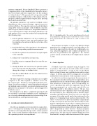
FIG. 12. Simulink model of the control algorithm used in closed- loop simulations. The green ports on the left are sources of syn- thetic measurements, the cyan ports is a sink of actuator com- mands.
We performed a number of scans over different design parameters for a simple potential control algorithm to ob- tain obtain upper and lower bounds for stabilizing the sys- tem, saturated amplitudes, and oscillation frequencies. In all cases, the perturbation was applied at 1 ms, and the control system activated when the displacement reached 5.2 cm.
A.
Control Algorithm
