
Page 8 - Positional stability of field-reversed-configurations in the presence of resistive walls
P. 8
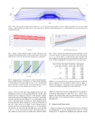
volume: a spheroid that just barely encloses the separatrix, a cylinder the plasma current.
of similar dimensions, or a spheroid that encloses the majority of
8
FIG. 4. Flux contours and toroidal current density at t = 1 ms. The green lines indicate some potential reasonable choices for the rigid
500 400 300 200 100
0
123456
Time [ms]
480 460 440 420 400 380 360 340
1 ms 2 ms
3 ms
123456 Minimum Displacement [cm]
FIG. 5. Range of axial stability moduli over time. Plotted are the minimum and maximum values for spheroidal rigid volumes with radius from 42 cm to 70 cm (and same elongation as separatrix).
FIG. 7. Time constants obtained from least squares fitting over dif- ferent time periods. Fitting was performed over the region where z0<z<z0+10cm,wherez0isgivenbythexaxisoftheplot.Dif- ferent graphs for the same perturbation time indicate initial condi- tions calculated with different assumptionts for the rigid volume.
25 20 15 10
5 0
1.0 1.5
2.0 2.5 3.0 Time [ms]
3.5 4.0 4.5
Time of initial pert. [ms]
1.0
2.0
3.0
Rel. Wall Conduct.
0.50 1.00 1.50 0.75
1.0 1.75 1.0
Fitted Time Const. [μs]
193.9 383.1 556.7 307.4 394.6 671.8 400.4
Normalized Time Const.
0.506 1.000 1.453 0.779 1.000 1.702 1.000
FIG. 6. Axial position of separatrix over time after initial pertur- bation at different times. Dotted lines are exponentials, with time constants fitted over the period where 2 cm < z < 12 cm (shaded in green). The time constants are 383.1 μs (for perturbations at 1 ms), 394.6 μs (for pert. at 2 ms) and 400.4 μs (for pert. at 3 ms).
stants to decrease with increasing displacement (since the driving force increases stronger than linearly). On the other hand, from the temporal evolution of the plasma equilib- rium (deduced from the higher time constants for perturba- tions later in time as well as figure 5), we would expect an in- crease of the fitted time constants for a later fitting window. It seems that this effect dominates over the non-linearity of the force. Since there is no single “correct” fitting window, we have chosen to use the fit with 2 cm < z < 12 cm, with an uncertainty of ±10% given by the difference to the fit with 1 cm < z < 11 cm. This is based on the observation that ini- tial conditions seem to have very little effect, and that earlier
TABLE I. Least square fitted exponential growth times for different initial conditions. The uncertainty is about ±10% (cf. figure 7). Values in the rightmost column have been normalized to the time constants obtained for nominal (1.0) wall conductivity.
values are expected to be more appropriate for comparison with linear approximations than later ones. Table I sum- marizes the growth times and associated uncertainties for different times of the initial perturbation using the selected fitting period.
D.
Comparison with linear model
Figure 8 compares the linearized driving force (obtained by multiplying Fzc by the displacement) with the actual driving force (computed by displacing the plasma current
z [cm] Stability Modulus [N/m]
Time Constant [ s]
