
Page 4 - Calibration and applications of visible imaging cameras on the C-2U advanced beam-driven field-reversed configuration device
P. 4
10E103-4
Granstedt, Fallah, and Thompson
Rev. Sci. Instrum. 89, 10E103 (2018)
FIG. 5.
horizontal and vertical angles.
C. Absolute photon response
The absolute photon response was measured ex situ for each filter using a broadband calibrated uniform radiance source (integrating sphere). As in the optical nonuniformity calibration, the optics were mounted in the re-entrant vac- uum viewport so that the calibration accounted for vignetting through the window. The radiance at a spectral line is obtained using the ratio of the filter transmission at that spectral line
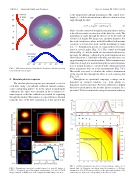
FIG. 6. Nonuniform correction for radial camera: [(a) and (b)] Images of LCD. (c) Computed optical throughput nonuniformity. [(d) and (e)] LCD image residuals. (f) RMS error of the computed nonuniformity correction.
to the integrated broadband transmission. The central wave- length (λc) of dielectric interference filters is a function of ray angle through the filter,
λc(θ)=λ0 1−(sinθ/neff)2, (2)
where λ0 is the central wavelength at normal incidence and neff is the effective index or refraction of the dielectric stack. The maximum ray angle through the filter is set by the trade-off of lens focal length, F/#, image size, and filter diameter. For this work, interference filters with full-width at half-maxima as narrow as 1.0 nm were used, and the maximum ray angle was ∼3◦. Transmission spectra of a typical filter were mea- sured at several angles [Fig. 7(a)]. The central wavelength followed Eq. (2), but the width also broadened with increas- ing angle. In addition, a sharp drop in peak transmission was observed at about 1◦, likely due to the filter anti-reflection coat- ing performing best at normal incidence. Filter transmission as a function of angle was modeled using the measured transmis- sion at normal incidence convolved with a Gaussian kernel whose parameters were fit to the measurements [Fig. 7(b)]. This model was used to calculate the relative transmission of the spectral line through the filter at each camera pixel [Fig. 7(c)].
Throughout an operational campaign, coatings can be deposited on viewport windows (e.g., from plasma re- deposition of getter material). Post-run calibration is helpful but leaves uncertainty in the absolute photon response for a given shot. To better estimate the viewport transmission history
LCD characterization: Normalized 2-D radiance with lineouts along
FIG. 7. (a) Filter transmission spectra for various incidence angles of col- limated light. (b) Gaussian convolution kernel fit parameters. (c) Relative transmission of the 650.0 nm spectral line in the upper-right quadrant of the camera detector, with (0, 0) corresponding to the detector center.
