
Page 9 - Demo
P. 9
042504-9
Rath et al.
Phys. Plasmas 24, 042504 (2017)
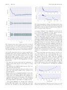
FIG. 7. Separatrix location, control coil currents, and control coil voltages in a representative linear, closed-loop simulation. In this case, the cycle time was 25 ls, the latency one cycle, and the overall gain 25. The figure shows one graph for each of the 8 control coils, but since the values for coils on the same side of the midplane are very close, only two graphs (green and purple) can be distinguished. Only the first 10 ms of a 30 ms simulation is plotted.
of 4.5 cm. The initial time was set to 1.4 ms to match the ini- tial displacement of the non-linear simulations. The control system activates when the displacement reaches 5.2 cm and immediately assigns a voltage of 6800 V to each coil. With inspiration from the terminology used for analysis of second order systems, we define the following quantities (for stabi- lized systems):
• The offset is the average position after the settling time (as defined below) has passed, in the limit of a long simulation.
• The amplitude is the RMS deviation from the offset, cal- culated over the same interval.
• The period is the average time that passes between cross- ings of the offset with a negative slope, calculated over the same interval.
• If the position is not eventually bounded by 65.2 cm (the displacement at which the feedback control activates), the settling time is not defined and the above quantities are calculated starting from the beginning of the simulation. Otherwise, the settling time is the earliest time at which the position returns to offset without exceeding 65.2 cm.
For a given simulation, we calculate these values by starting with a high estimate of the settling time (3 ms) and then iterate the calculation of offset and settling time until
FIG. 8. Period and amplitude for different feedback gains in linear, closed- loop simulations. The cycle time and latency were held fixed at 10 ls. The apparent jump at gain 70 is caused by the plasma position asymptotically approaching zero (with a superimposed oscillation) instead of quickly set- tling to an oscillation around a constant offset.
convergence. In Figure 7, the settling time is 3.1 ms, the off- set is 0.05cm, the amplitude is 0.4cm, and the period is 452 ls. Linear simulations were run until 30 ms.
Figures 8–10 show the dependence of period and ampli- tude on feedback gain, cycle time, and latency. The general trends are not surprising. Higher gain results in faster periods and smaller amplitudes until a threshold is reached at which the feedback system switches between the minimum and maximum voltage on every cycle. Slower cycle times and higher latencies increase both the amplitude and period of the stabilized position. All offsets (not plotted) are between 1 cm and þ1 cm with no clear dependency on gain or cycle time and an approximately linear dependence on latency. Settling times (not plotted) are between 2.4 ms and 4.4 ms and show no clear dependence on any parameter (including gain).
A more interesting observation is that for very fast cycle times and low latencies, the control algorithm starts to per- form worse. This is because in this regime, the coil currents are shielded out by the resistive wall—the algorithm switches very quickly between positive and negative vol- tages, but the plasma feels almost no change in the total magnetic field due to the induced wall eddy currents. An obvious improvement to the control algorithm is to apply a filter to the coil currents before calculating the weighted
FIG. 9. Period and amplitude for different cycle times in linear, closed-loop simulations. The gain was fixed at 25, and the latency was held at one cycle.
