
Page 2 - Suppressed ion-scale turbulence in a hot high-beta plasma
P. 2
053512-2 Matsumoto et al.
Rev. Sci. Instrum. 87, 053512 (2016)
Therefore, the density of the CT should be >4.8 ⇥ 1020 m 3 in the case of C-2. By adjusting the voltage applied between the electrodes, the velocity of the CT can be modified. On the other hand, the density is decided by the amount of gas particles between electrodes. To change the amount of gas between electrodes, the space between electrodes could be modified or higher pressure could be used. But, if we use wider spacing, breakdown does not occur. Therefore, we decided the distance between electrodes based on past CT injection experiment on the tokamaks (e.g., TdeV, STOR-M, JFT-2M).
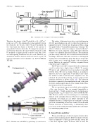
FIG. 2. Schematic view of the MCPG. (a) global image. (b) vertical section.
The surface of the inner electrode is coated with tungsten (0.2–0.3 μm in thickness) in order to reduce the production of impurities from the electrode into the plasmoid. This coating was applied with a “Vacuum Plasma Spraying” technique. The e↵ect of refractory electrode coatings is shown by Brown.9 Therefore, we used a tungsten coating. The inner electrode consists of a cylindrical part and a head part. The cylindrical part has a cavity where the bias coil can be inserted from the end flange. The head of the inner electrode is solid tungsten machined into a hemispherical shape. The head is replaceable with a longer one to extend the length of the acceleration region. Therefore, if a greater CT velocity is required, then a longer head can be employed.
The CT injector should be separated from the confinement vessel for safety due to high voltage (>20 kV). To separate CT injector and confinement vessel, an insulator is installed between them. We used a ceramic break as an insulator. Therefore, the CT’s trapped flux would di↵use and contact the insulator which would introduce impurities into the plasmoid. To prevent this problem, we have employed the extension electrode as shown in Fig. 2(b). The extension electrode is connected to the muzzle near the end of the outer electrode, and through the inside of the ceramic break. Then, the extension electrode is grounded.
The two gas injection ports are welded on the mid-plane of the outer electrode. They are arranged tangentially as shown in Fig. 3. Usually, an injection port of neutral gas is arranged axially (e.g., CT injector for; TdeV, STOR-M, JFT- 2M). However, in that case, the neutral gas is not uniformly di↵used in the azimuthal direction. Therefore, by arranging tangentially, the neutral gas can di↵use uniformly in the azimuthal direction. X-shaped ports are arranged to prevent gas from accumulating around the ceramic break installed between electrodes as shown in Fig. 2. Alternatively, these ports can be used to pump neutral gas quickly after a discharge by connecting a pump system.
B. Gas pu valve and driver
We can select the type of valves from piezoelectric valves and fast valve for plasma gun test. However, the piezoelectric valves are di cult to control gas flow with this system due to the slow response speed. If slower valve is used, the
FIG. 1. Schematic view of compact toroid formation by MCPG.
