
Page 3 - Suppressed ion-scale turbulence in a hot high-beta plasma
P. 3
053512-3
Matsumoto et al.
Rev. Sci. Instrum. 87, 053512 (2016) TABLE I. Power supplies for CT injector.
Capacitances (F)
withstand high voltages applied on the inner electrode.
D. Power supplies
The MCPG has been tuned with a high voltage pulse to achieve higher ionization-rate discharges with lower gas pressure. The power supply of the MCPG consists of a main bank (fast discharge for CT generation) and a bias bank (slow discharge for bias field) as listed in Table I. The main discharge gun current is supplied by a 40 kV, 12 μF (4 μF ⇥ 3) fast capacitor bank that is typically charged to 20 kV because of the 24 kV stand-o↵ voltage limit of the ceramic breaks between electrodes. A crowbar switch is installed on the main bank circuit to create the characteristic discharge. Thyristors are used as the switches for discharge and crowbar circuits.
For the bias discharge, electrolytic capacitors with a maximum voltage of 450 V are employed. The capacitance of bias circuit must be large to make a long pulse magnetic field in order to penetrate through electrodes. It is relatively easy to change the bias coil because the frequency of bias field is decided mainly by capacitance. The frequency of bias current fbias to penetrate through the electrode is estimated by skin e↵ect f = ⇢/⇡ 2μ, where ⇢, , and μ are resistivity of the conductor, skin depth, and magnetic permeability, respectively. In our electrodes, the frequency fbias needs to be much slower than 20 kHz because they are 3 mm in thickness. In our bias bank with 20 μH bias coil, the frequency of bias
A shunt inductor (⇠20 μH) is installed between the electrodes to damp the released energy in case breakdown between electrodes does not occur. The frequency of inductance find is approximately 10 kHz. Therefore, the current flowing into the shunt inductor is negligible compared to the main discharge current during plasma formation. The waveform of gun current is shown in Section III A.
III. EXPERIMENTAL SETUP AND RESULTS
For test working of the MCPG, we connected it to di↵erent test chambers with diameters of 10 cm and 37 cm, respectively. Figure 4 shows schematic view of the MCPG attached on the test stand. The test chamber with the 10 cm diameter has 4 radial ports at equal intervals of 90 and some major plasma parameters were measured (density, temperature). This small test chamber was also connected to the larger test chamber for further diagnosing.
Maximum voltage (V) ⇠20 k
⇠300 (Radix Wire Company, HQA22T007) for the bias coil can
Main bank (gun) 12 μ Bias bank 50 m
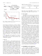
FIG. 3. Schematic of gas pu↵ system. (a) Cross section drawing of the gas pu↵ port. (b) Typical waveform of the gas driver used.
injected neutral gas will a↵ect the core plasma by di↵using into the confinement vessel. Thus, this type of valve system is inadequate for CT injector. Hence, we employed fast solenoid valves (Parker Hannifin Corp., model: 009-0442-900) in this system. To insulate between gas valves and outer electrode, a ceramic break (MPF, Inc., A2596-1, 30 kV) is installed between the gas port and the gas valve as illustrated in Fig. 3(a). The pu↵ valves are typically driven by a 28 VDC pulse by design. However, to realize a fast response of the valves, a high-voltage short pulse is initially applied (⇠350 V at the peak, damping time ⇠2 ms) in addition to the 28 VDC pulse.
The trigger pulse for the gas pu↵ valves is shown in Fig. 3(b). Each pu↵ valve is connected to one of the two trigger terminals on the gas driver. The output duration of the 28 VDC pulse is adjustable.
C. Bias coil
To produce CTs (i.e., spheromak-like plasmoids) by the MCPG, a bias magnetic flux is required for magnetizing the plasma. Other typical MCPGs have bias coils that are wound on the outer electrode. With externally wound bias-coils, baking the MCPG is di cult because of the heat load on the wires wound to form the bias coil. The MCPG described herein has an internal bias coil, installed inside the inner electrode as shown in Fig. 2(b). Thereby, as the bias coil is not fixed to the inner electrode, the bias coil can be moved axially and can be easily arranged for di↵erent bias coil configurations (shorter, longer, turns, etc.). In addition to allowing for di↵erent bias coil configurations, there is also the advantage of avoiding heat loading during baking. The bias coil is wound on a rod (22 mm in O.D., PVC) has 60 turns across 2 layers with inductance of approximately 20 μH and measures approximately 18 cm in length. The cable
can be estimated from f ⇡ 1/2⇡pLC, where L
current f
and C are inductance and capacitance, respectively. Then, the frequency of bias current fbias is approximately 160 Hz. This result satisfies the electrode penetration condition.
bias
