
Page 4 - Suppressed ion-scale turbulence in a hot high-beta plasma
P. 4
053512-4 Matsumoto et al. Rev. Sci. Instrum. 87, 053512 (2016)
FIG. 4. Schematic view of the MCPG attached on the test stand to measure the ejected CT.
Diagnostics on the test stand include a Rogowski coil located at the end of the ceramic break between the electrodes to measure the gun current, a resistor chain connected between electrodes to measure the gun voltage, a triple Langmuir probe which has floating double probe to measure ion saturation current and floating potential measurement (single probe)10 located at r ⇠3 cm (wall radius ⇠5 cm) on the smaller test chamber, a He-Ne laser interferometer (single-pass) across the diameter of drift tube11 on the smaller test chamber to measure line integrated electron density, and 6 focused photo-diodes to measure time-of-flight (TOF) for each ports along the device axis as shown in Fig. 4.
A. Typical current and voltage
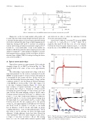
Typical bias currents are approximately 220 A with the charging voltage Vbias at 100 V as shown in Fig. 5(a). The magnetic field at the center of bias coil is approximately 133 G.
The relationship of gun current and voltage is the most important parameter for the ejection of plasmoids from the MCPG. As mentioned above, ejection velocity of the plasmoid is determined by the Lorentz self-force. In this section, we show the relationship between gun current, voltage, and the conditions needed to eject the plasmoid. Typical discharges of the MCPG are shown in Fig. 5. The time origin is set to the time of plasma formation. Figure 5(b) shows the time evolution of typical waveforms of the gun voltage and current. The voltage is obtained by a Pearson probe measuring the current through a 4.5 k⌦ resistor across the gun’s breech. The main charging voltage is 20 kV with a resultant current betwe⇤en the electrodes of ⇠250 kA at the peak (t = ⇠2 μs). The overall circuit e ciency is defined as Einj/1⁄2CV2 with Einj = IgunVgun dt, the injected energy from the main bank, Igun is gun current, and Vgun is gun voltage between electrodes. For the conditions above, the injected energy, Einj, was approximately 1.6 kJ while the stored energy was about 2.4 kJ (V = 20 kV, C = 12 μF), so our circuit has an e ciency of 66.7% On the other hand, an energy coupling e ciency is ⇠24% for typical plasma guns.12 From this result, it can be said that our device has high circuit e ciency. A high e ciency device has been observed in other experiment.13 However, pulse duration of this device is longer (⇠3 ms) than our device (⇠20 μs). The causing factor is to use 36 coaxial cables between capacitor bank
and electrodes in order to reduce the inductance between electrodes and capacitor bank.
A necessary condition to eject the CTs from the MCPG isgivenby g=μ0Igun/b= c=⇡/ d,14wherebis magnetic flux made by the bias coil, d is the distance between the electrodes in the formation region, c is derived from the size of the MCPG. From this equation, constants
FIG.5. Typicalwaveforms,(a)typicalbiascurrent(chargedvoltageonbank: 100 V), (b) typical discharge on CT injector (arbitrary polarity). The time origin is set to the time of plasma formation.
