
Page 2 - Equilibrium properties of hybrid field reversed configurations
P. 2
Nucl. Fusion 57 (2017) 076018 T. Asai et al
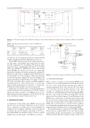
Figure 2. A schematic diagram of the multi-pulse discharge circuit, which includes the charging circuit, main bank, snubber circuit and CT injector.
Table 1. The typical plasma parameters of the C-2U FRC and injected CTs.
Particles (×1019)
FRC 1.0–1.5 CT 0.5–1.0
Temperature (eV)
600–800 (total) 20–30 (electron)
Poloidal ux Energy (mWb) (kJ)
5–7 5–7 0.4 0.1–0.3
[4]. However, the development of effective fueling methods remains a signi cant task for the FRC fusion reactor core.
Not just FRCs, but most magnetically con ned fusion reac- tors will require central fueling, and ice pellet injection cannot meet this requirement [5]. Accordingly, CT injection experi- ments have been experimentally investigated in tokamaks (TdeV [6], JFT-2M [7], STOR-M [8]) and a eld-reversed pinch (TPE-RX) [9]. Steady state reactors also require high repetition rate fueling at low density and magnetic perturbation. Therefore, in this work, a repetitively driven CT injector was developed with a rate of up to 1 kHz via a multi-stage discharge circuit [10]. Repetitive multiple CT injection minimizes the density and magnetic perturbation due to the impact of injected CT on the core plasma. Also, to reduce toroidally asymmetric momentum injection, counter CT injection—i.e. the injection angles are horizontally opposed to cancel the n = 1 motion trig- gered by injected momentum—has also been proposed.
In this paper, we report the proof of concept experiments of CT injection that have been performed on C-2/C-2U. Counter CT injection with a frequency of 0.5kHz has been success- fully demonstrated with a fueling rate of 20–30% in the total particle number per single CT injection [11, 12].
2. Experimental setup
A magnetized coaxial plasma gun (MCPG) type [13] CT injector has been developed exclusively for the C-2/C-2U devices, primarily for fueling. The developed MCPG was optimized on a test chamber, which has a transverse eld coil to simulate the external magnetic eld of the C-2U device. The tuned MCPG was mounted on the C-2U device and the multiple injection and response of the FRC was evaluated.
Figure 3. A schematic diagram of the PI system on the CT injector. 2.1. Developed plasma gun
Figure 1 shows a schematic of the developed MCPG [1]. It consists of a set of coaxial cylindrical electrodes made of stain- less steel, a bias coil and four gas injection ports, which are arranged tangentially on the outer electrode. The outer diam- eter of the inner electrode and inner diameter of the outer electrode are 54.0mm and 83.1mm respectively. The inner electrode is coated with tungsten to reduce the impurity in ux. The bias coil is wound on a PVC rod (22mm O.D.), has 60 turns across 2 layers and a length of 18 cm. Breakdown of the MCPG can be controlled by a conducting shell wound around the outer electrode. A plasma ring is generated within the gap between the electrodes and is accelerated by Lorenz self-force. During this acceleration process, toroidal current is induced by a poloidal ux interlinked with the plasma ring. Then, the magnetized spheromak-like CT is ejected from the MCPG.
To refuel the particles of long-lived C-2U FRCs, multiple CT injections are required. Thus, we have developed a multi- stage discharge circuit, as shown in gure 2, for a multi-pulsed CT injection [10]. The drive frequency of this system can be
2
