
Page 3 - Equilibrium properties of hybrid field reversed configurations
P. 3
Nucl. Fusion 57 (2017) 076018
T. Asai et al
Figure 4. A schematic of the CT injector test stand and diagnostic setup.
adjusted by up to 1 kHz, the number of CT shots per injector is two, and the system can be further upgraded for a larger number of injection pulses. The charging voltage of the 125 μF capac- itor bank is approximately 10 kV and the peak gun current is about 200 kA per single discharge. The rise time of the cur- rent pulse is 10 μs and the half width is 15 μs. Table 1 lists the typical parameters of the generated CT on the test stand and the target of the C-2U FRC. The developed MCPG achieved supersonic ejection velocity in the range of ~100 km s−1. The key plasma parameters of electron density, electron temperature and the number of particles are ~5 × 10²¹ m−3, 20–30 eV and 0.5–1.0 × 10¹⁹, respectively.
To improve the performance of fueling by the MCPG, a pre-ionization (PI) technique has also been developed. A sche- matic of the PI system on the MCPG is illustrated in gure 3. This can decrease the trailing neutral gas from the CT injector, which potentially cools the FRC plasma. The PI electrode, which is made of semi-rigid coaxial cable with a Te on insu- lator, is mounted on the same axial section with gas-inlet ports. The inner and outer electrodes are made of copper and the diameter of the outer electrode is 6.5 mm. The plasma dis- charge is initiated between the electrodes on the end surface in the same way as a pulsed-plasma thruster (PPT). Then the plasma is accelerated by Lorentz self-force and injected into the gap between coaxial electrodes. This reduces the amount of initial neutral gas required to initiate the breakdown of CT formation. Also, a higher percentage of the injected gas is used to form the plasmoid. This reduces the in ow of the trailing neutral gas into the main con nement vessel.
2.2. Test stand
The test stand for the CT injector is illustrated in gure 4 [14]. This test stand consists of three sections: a CT injector, a drift tube and a transparent glass tube with a transverse magnetic eld. The global behavior and typical plasma parameters of the ejected CT in the magnetic eld, which are equivalent to the external magnetic eld of C-2U FRC, were evaluated. In the drift tube, the velocity, density, temperature, length and mass of the CT were measured. In the transverse eld region, the penetration depth and the trajectory of the CT were observed. The transverse magnetic eld is generated by a pair
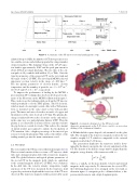
Figure 5. A schematic drawing of (a) the CT injector and diagnostic arrangements on the C-2U device, and (b) a cross-section drawing of the con nement chamber.
of Helmholtz-like square-shaped coils mounted on the glass tube. The strength of the transverse magnetic eld on the test stand is roughly 0.1 T, which is comparable to the external magnetic eld of the C-2U device.
The penetration depth into the transverse eld is deter- mined by the kinetic energy Ek, the velocity and density of the CT. The density of the kinetic energy must be higher than the magnetic energy density of the transverse eld, i.e.
12 12 2ρv ⩾2μ Bex,
0
where ρ, ν and Bex are the mass density, velocity and external magnetic eld, respectively. To characterize the ejected CTs, the following diagnostics were arranged on the test stand, as shown in gure 4: a magnetic probe, collimated bers, a dis- persion interferometer and a triple Langmuir probe.
3
