
Page 2 - Particle and heat flux diagnostics on the C-2W divertor electrodes
P. 2
10J110-2 Griswold et al.
Rev. Sci. Instrum. 89, 10J110 (2018)
FIG. 1. Exterior view of the C-2W experiment at TAE Technologies.
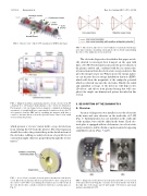
FIG.2. Magneticfieldlinesandplasmadensity(coloredcontours)inC-2W calculated by a 2-D magneto-hydrodynamic code,2 shown for illustration. Fast magnetic coils can change between magnetic configurations during an experiment: (a) straight field lines connecting the formation section to the CV are required to form the FRC and (b) expanding the magnetic field lines to connect to the inner divertor electrodes provides better control of the radial electric field in the plasma.
which presents a “reverse” mirror field to stop cold electrons from entering the CV from the divertor. The field expansion should also reduce the potential drop in the sheath in front of the electrodes, robbing secondary electrons of a parallel accel- eration that might otherwise propel them through the reverse mirror.9
FIG. 4. The electron and ion loss cone boundaries of an ideal isolated mag- netic mirror plasma considering only magnetic effects (black) and including the effect of the ambipolar electric field (red).
The electrode diagnostics described in this paper are ide- ally situated to investigate heat transport on the open field lines of C-2W. Pyrobolometers measure the power density of the plasma outflow and, combined with the ion current den- sity measurement from the electrostatic energy analyzers, this gives the energy lost per ion. What is more, the energy analyz- ers can measure the ion energy distribution function (IEDF), which will show the magnitude of the ambipolar potential which accelerated ions into the electrodes. Finally, the radial and azimuthal coverage of the detectors will help resolve 2D effects, and effects from plasma biasing that will com- plicate the simple one-dimensional picture described in this section.
II. DESCRIPTION OF THE DIAGNOSTICS A. Overview
An array of diagnostics was installed across the electrodes in the inner and outer divertors on the north side of C-2W (Fig. 1). Instrumentation was not installed on the south side of the machine, but could be added in the future. Each elec- trode plate is equipped with two bolometers, two electrostatic energy analyzers, and two thermocouples mounted at opposing azimuthal locations (Figs. 5 and 6).
FIG.3. Asetoffourconcentricelectrodeplatesismountedineachdivertor vessel. Electrodes in the inner divertors (pictured above) have a large hole in the center to allow CTs to pass during the formation process. Electrodes in the outer divertor have a smaller central hole that houses a plasma gun (see Fig. 6).
FIG. 5.
of the inner divertor showing the concentric electrode mounted to the wall on the right side of the image and (b) photograph of bolometers and energy analyzers installed in C-2W.
Diagnostics on the divertor electrode plates in C-2W: (a) cross section
