
Page 3 - Particle and heat flux diagnostics on the C-2W divertor electrodes
P. 3
10J110-3 Griswold et al.
Rev. Sci. Instrum. 89, 10J110 (2018)
FIG.6. MapofdiagnosticsonthedivertorelectrodesinC-2W.
B. Modular design
The energy analyzers and bolometers have a modular design to simplify installation and maintenance. The signal cables are terminated in a connector plug, which fits inside a mounting structure that bolts to the electrode plate (Fig. 7). The mounting structures are angled to orient each analyzer so that its axis points roughly parallel to the local magnetic field. The diagnostic’s internal components are built on an alumina base- plate that plugs into the connector plug for the signal cables. The enclosure is completed with a stainless steel 316 (SS 316) cap that screws onto the mounting structure.
C. Energy analyzer
1. Method of operation
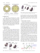
The energy analyzer follows standard design rules that are described, for example, in Refs. 10 and 11. It consists of a current sensor positioned behind three gridded electrodes (Fig. 8). An attenuation grid at the aperture of the device is held at potential Ua, which is equal to the potential of the elec- trode plate that the analyzer is mounted on. The attenuation grid sets the potential at the entrance to the device and reduces the incident plasma density by a factor of 30 to prevent space- charge electric fields12 from impeding current flow inside the device. Next, the ion grid is biased to a potential Ui that repels ions with kinetic energy below q(Ui −Ua). For Ui = Ua, no ions are repelled and the current sensor will measure the full ion current density that passes through the attenuation grid. Alter- natively, Ui can be swept through a potential large enough to repel all of the incident ions. This produces a current-voltage
FIG.8. Explodedviewoftheenergyanalyzer.Allmaterialsarestainlesssteel 316 except for the alumina baseplate and tungsten attenuation grid.
trace whose derivative is equal to the ion energy distribution function. Finally, the electron grid is biased to several hun- dred volts below the case potential to repel plasma electrons from reaching the current sensor and to prevent secondary electrons from escaping off the surface of the current sensor (Fig. 9).
2. Energy analyzer construction
A tungsten attenuation grid is welded to the SS 316 screw- on cap that encloses the diagnostic while the current sensor, electron grid, and ion grid are attached to the alumina baseplate with ceramic cement. The electron and ion grids are composed of a SS 316 frame that supports two SS 316 meshes, which are separated by a spacer ring to form a “pill-box” shaped electrode. This arrangement is better than a single grid at controlling fringing fields around the mesh holes.13 A second spacer ring covers the edge of the thin front mesh to prevent electrical arcing. The SS 316 spacer rings also serve as baffles, extending radially inward from the frame to shield the alumina baseplate from stray charged particles [Fig. 10(a)]. It is impor- tant to shield all insulator surfaces in a particle analyzer from the path of charged particles. If not properly shielded, insu- lators will build up static charge that can distort the desired electric fields in the device.10
The electron and ion grid meshes are laser-cut from a 3 mil thick 316 stainless steel sheet. They have 500 × 1000 μm rectangular holes separated by 70 μm wide bars. The attenua- tion grid is laser-cut from a 75 μm thick tungsten sheet using a special process developed by Oxford Lasers, Inc. to create conical holes that are tapered at a 54◦ angle. This taper allows the attenuation grid hole radius to be smaller than the local Debye length (∼100 μm) without blocking large-angle ions from entering the device (ions are magnetically collimated10
FIG.7. Explodedviewofanenergyanalyzershowingitsmodulardesign.
FIG.9. Potentialdistributioninsidetheenergyanalyzer.
