
Page 5 - Particle and heat flux diagnostics on the C-2W divertor electrodes
P. 5
10J110-5
Griswold et al.
Rev. Sci. Instrum. 89, 10J110 (2018)
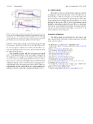
FIG.13. Datafromthecentralelectrodeplateinthenorthouterdivertor,shot no. 104988: (a) ion current density measured by energy analyzers (red = top analyzer and blue = bottom analyzer) plotted against the electrode biasing current divided by the electrode area and (b) power density measured by pyrobolometers (red = top bolometer and blue = bottom bolometer).
inductive voltage spikes as high as 25 kV. Each diagnostic and its electronics must, by necessity, be electrically connected to the electrode plate to which it is attached, and the whole sys- tem must maintain electrical isolation from ground and from the other electrode plates.
Data acquisition boards and other electronics are housed in 19′′ rack mount modules, with one module serving all of the diagnostics on a single electrode plate. The modules sit on top of 5 kV class utility grade insulators that have a short- timescale basic insulation level (BIL) rating of 70 kV. Network and trigger signals connect over fiber optics, and power is pro- vided through isolation transformers rated to 30 kV. There are eight modules in total, and stacks of two or three modules are housed in cabinets connected to machine ground for safety.
III. SAMPLE DATA
Initial data on the ion current density and power density reaching the central electrode plate of the outer divertor are shown in Fig. 13. The electrode plate was biased roughly 1 kV below machine ground during the displayed shot. Given that the maximum electron temperature measured in the core of the machine for this shot was 200 eV, the electrode biasing current should be carried almost entirely by ions. The close agreement between the current density measured by the energy analyzers and the measured biasing current [Fig. 13(a)] serves as an initial validation of the diagnostic.
ACKNOWLEDGMENTS
The authors thank our shareholders for their support and trust and all fellow TAE staff for their dedication, excellent work, and extra efforts.
1M. Binderbauer et al., AIP Conf. Proc. 1721, 030003 (2016).
2L. Galeotti, D. C. Barnes, F. Ceccherini, and F. Pegoraro, Phys. Plasmas 18,
082509 (2011).
3H. Gota et al., Nucl. Fusion 57, 116021 (2017). 4L. C. Steinhauer, Phys. Fluids B 4, 4012 (1992). 5R. F. Post, J. Nucl. Mater. 76-77, 112 (1978).
6R. F. Post, Nucl. Fusion 27, 1579 (1987).
7L. S. Hall, Nucl. Fusion 17, 1579 (1977).
8T. C. Simonen, J. Fusion Energy 35, 63 (2016). 9D. D. Ryutov, Fusion Sci. Technol. 47, 148 (2005).
10A. W. Molvik, Rev. Sci. Instrum. 52, 704 (1981).
11S. Stephanakis and W. H. Bennett, Rev. Sci. Instrum. 39, 1714 (1968).
12I. Langmuir, Phys. Rev. 2, 450 (1913).
13D. C. Faircloth, “Technological aspects: High voltage,” CERN Yellow
Report CERN-2013-007, CERN, 2014, pp. 381–419.
14J. Cooper, J. Sci. Instrum. 39, 467 (1962).
15G. Fiksel, J. Frank, and D. Holly, Rev. Sci. Instrum. 64, 2761 (1993).
